 |
| values actually mapped correctly = some semblance of control. mapping painstakingly / experimentally determined |
 |
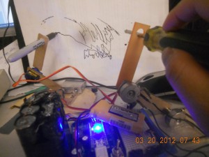
| the setup |
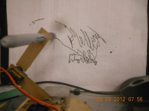
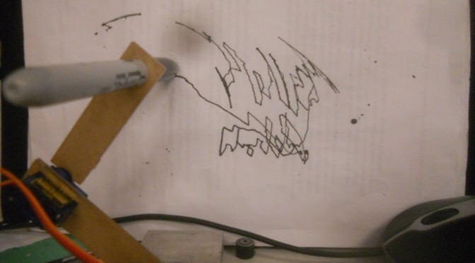
actually very difficult to write words even with the arm controller (versus twiddling some potentiometers to control the arm), because the potentiometer to servo mapping isn’t precise and there’s a lot of slop (e.g. look at the dead space around the screwdriver)
time elapsed: probably 1 hr including trying to figure out how to draw things and documenting ^^ (~40 minutes to code this and map the values)
/**
* @file: RC control of servo
*
* @description
* theta1 = bottom joint pot value, theta2 = top joint pot value
* these were experimentally determined,
* I had one leg of pot connected to sig5v, the other to a voltage
* divider setup with a 1kohm=R2 and being read to A0 or A1 respectively
*/
#include <Servo.h>
Servo servo1;
Servo servo2;
int theta1;
int theta2;
int map1;
int map2;
void setup()
{
// pinMode(1, INPUT);
// pinMode(2, INPUT);
Serial.begin(9600);
servo1.attach(2,500,2400);
servo2.attach(3,500,2400);
}
void loop()
{
theta1 = analogRead(A1);
theta2 = analogRead(A0);
// map1 = map(theta1, 163,380, 0,130);
map1 = map(theta1, 163,360, 0,130);
// map2 = map(theta2, 1017,275, 0,160);
map2 = map(theta2, 1017,264, 3,150);
servo1.write(map1);
servo2.write(map2);
Serial.print(“theta1 “); Serial.print(theta1);
Serial.print(” map1 “); Serial.print(map1 );
Serial.print(” theta2 “); Serial.print(theta2);
Serial.print(” map2 “); Serial.print(map2);
Serial.println();
delay(20);
}

