I recently got access to a friend’s server running a video generation deep learning model, MiniMax H3 (by the eponymous MiniMax), and on a whim
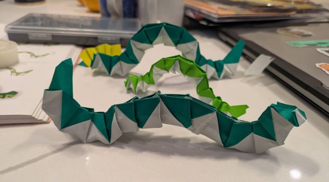
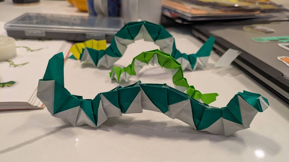
I gave it the picture of origami caterpillars (mentioned in a previous post) and wrote “Generate a video where the origami caterpillars in the attached image move.”
The result was honestly pretty impressive but not quite what I wanted.
Try 2
So I added in “The caterpillars should move across the screen, not just wriggle”. I liked the results a lot more (this is the one at the top of the post).
Wow!! They’re so wriggly 😀
the spiral
This was followed by several rounds of attempting to fix the video further in various ways, but getting worse results each time. The main issue is that the caterpillar all the way in the back is scrunching backwards (obviously the eyes are the side with a few extra folds, can’t you tell? XD) instead of scrunching forwards. So I asked it to fix that, but then the tape started moving with the caterpillar, and the caterpillars moved slower and only did half a scrunch instead of a full wriggle, and kinda skidded around the book, etc. Alas.
subtleties
there are little subtleties that show this is not really real (i.e. I didn’t go forth and make stop motion by moving my little caterpillars). The table actually has gray-ish stripes running through it that the model “interprets” as shadows that disappear halfway through the image, if you look closely.
technical details
As mentioned earlier, this was running a Minimax H3 model with a “reference-to-video” checkpoint. The reference is a text prompt and optionally 1-2 videos. The “prompt” per the minimax docs is actually quite detailed and written by an LLM that then calls the video generation model.
Write a structured prompt file (markdown + YAML frontmatter) with shot descriptions, dialog, soundscape, music
Load it into a ComfyUI workflow (MiniMaxH3ImageToVideo node)
Submit via ComfyUI API → poll for completion → download the video
~5-6 min per 10s clip on a 64GB GPU, run sequentially (no parallelization)
It's image-to-video with integrated audio (dialog, sound effects, music all in one pass).
Each call returns with a video and some details, here’s what it returned with the first video prompt:
What I did:
Used your attached image as the I2V reference (Picture 1) for MiniMax H3 on the MITERS-XXXXX ComfyUI (port XXXXX)
Wrote an I2VA prompt describing the caterpillars' segmented paper bodies undulating and inching forward with a rippling crawling motion, while the camera slowly pushes in
16:9 widescreen, 0.4 MP, turbo mode, 8 seconds, seed 42

The model preserved the original image as the first frame and animated the caterpillars moving from there. If you'd like a different style of motion (e.g. more dramatic movement, different camera angle, longer duration, or higher quality with --no-turbo), let me know and I can re-generate with adjusted parameters.
I2VA = image to video with audio. ComfyUI is a way to run generative AI models that well, generate images/videos/audio.
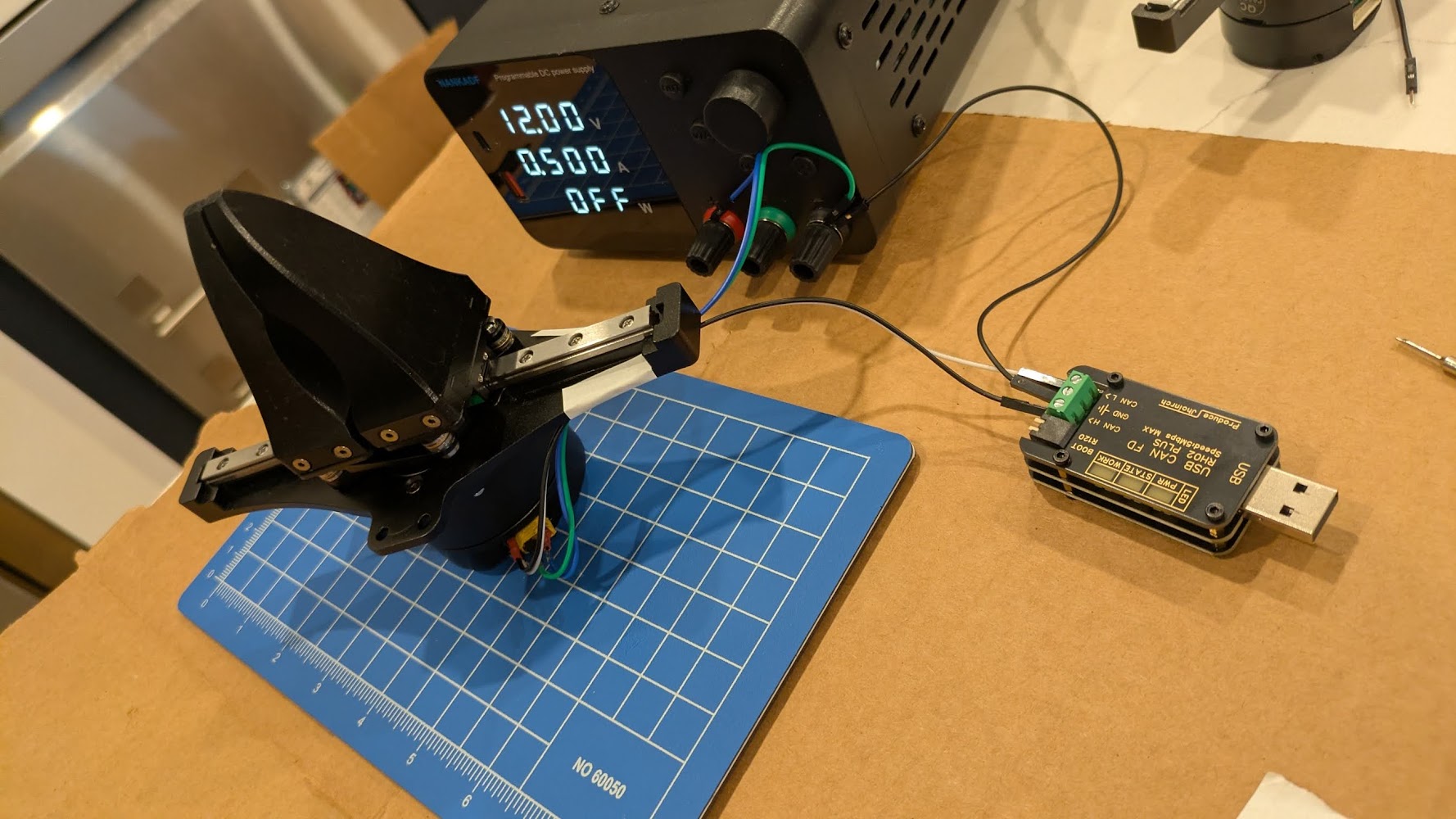
I got a gripper from some very nice SteadyWin folks at the boston robotics expo (part of boston robotics week / boston tech week) and finally got it working last week!! going to attach it to the UR5 once I’m done with the mount design.
After chatting with the steadywin folks on wechat, I got a link to their wiki.
The way these quasi direct-drive (QDD — has small planetary gearbox, not direct drive) brushless DC (BLDC) motors with integrated controllers (driver is built into the housing) work: you write to a register to control the motor and read from the register to get statuses.
On to the practical part:
Hardware setup
Get a Steadywin gripper (in the $150-200 range after shipping and fees)
Buy a bench power supply while you’re at it, they’re so light nowadays ?! The motor wants ~24V.
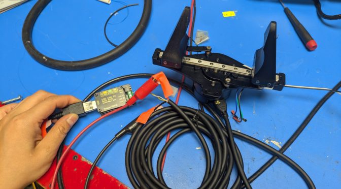
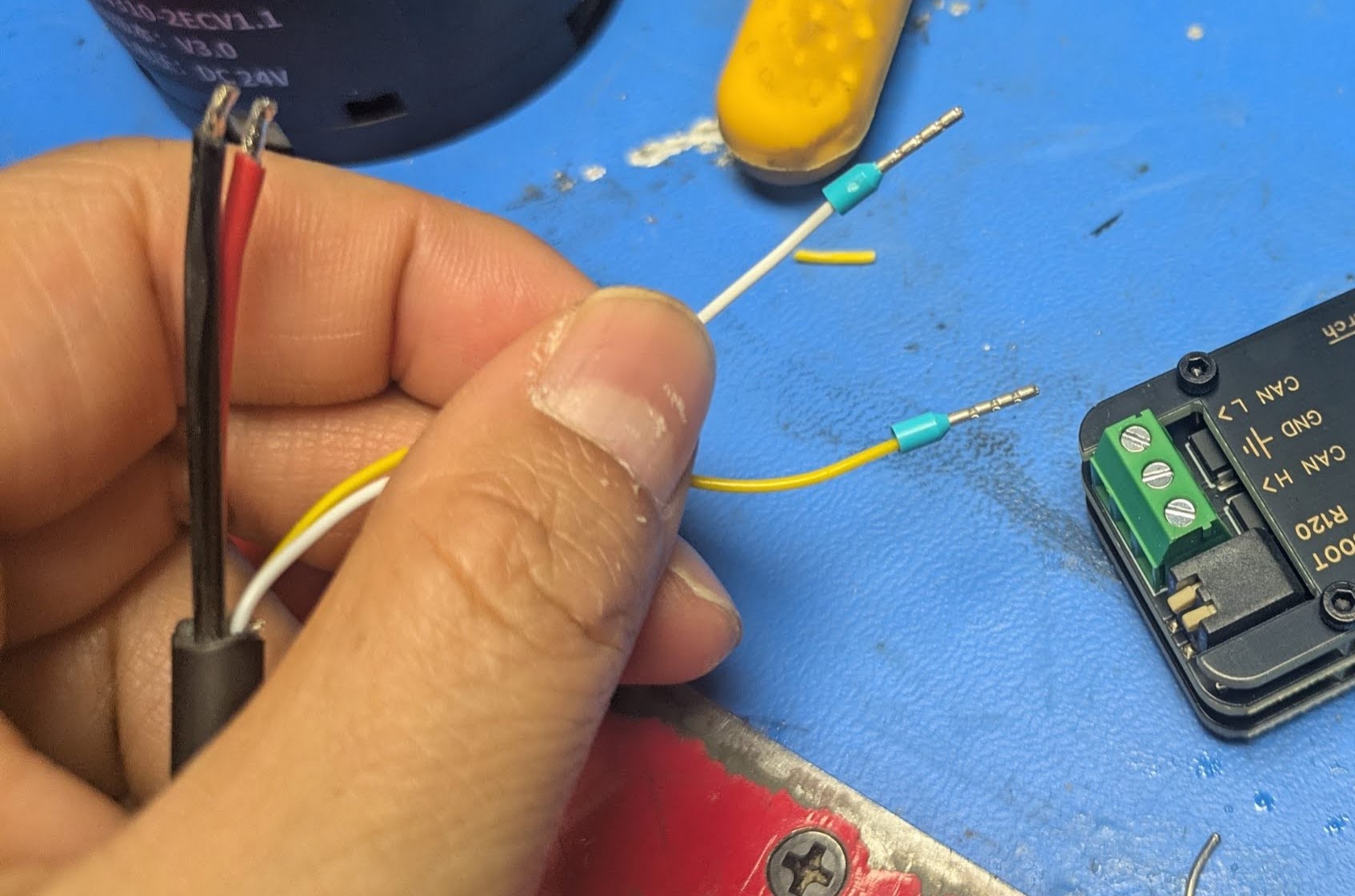
The XT30(2+2) consists of the fat motor power wires and two small signal wires. [6]
Plug in the cable, then connect to 1) the power supply and 2) the USBCAN device.
After wiring up the gripper, make sure to also:
** Connect USB CAN to laptop. **
** Turn on power to motor **
Don’t forget the above steps 🙂
Software setup
I got this working in Linux with the Steadywin motors.
In a nutshell:
$ uv venv
$ uv pip install python-can

$ sudo slcand -o -c -s8 /dev/ttyACM2  # [1]
$ sudo ip link set can0 up txqueuelen 1000 # [2]

# In a new terminal:
$ candump can0 # Listen to all the CAN messages back and forth
CANSEND? CANDO!
Sending CAN commands by hand
The overall flow
Check the motor is talks back and where it thinks it is using #280204 (ask for current position, should get a response from the motor), #21000103FFFFFF (set to position control), #34000101FFFFFF (set position to zero so we don’t get unexpected big movement — this needs to happen while torque is off, and we should get 01 in response, not 00), #00020101FFFFFF (torque on), #14020400040000 (command a position), #00020100FFFFFF (torque off).
The commands I used
cansend can0 001#01                  # ping — confirm it answers
cansend can0 001#02                  # status
cansend can0 001#280204              # read position
cansend can0 001#21000103FFFFFF      # mode = position (0x03, FFFFFF is for padding)
cansend can0 001#280204              # read position
cansend can0 001#34000101FFFFFF      # [3] set position to zero -- should get 01 as response, not 00 !
cansend can0 001#280204              # read position
cansend can0 001#00020101FFFFFF      # torque on (0x01)
cansend can0 001#14020400040000      # goal +1024
cansend can0 001#280204              # read position
cansend can0 001#00020100FFFFFF      # torque off (0x00)
cansend can0 001#02                  # check motor still alive. I use this because it's easy to remember
SUCCESS!!!!!!!111111!!!
The first high was when the motor actually talked back, the second was when it finally moved !!!!!!!!!!!!111111111!!!!!!!!!!!!!1
Parenthetical Notes
[1] Use sudo dmesg | tailto find the port, you’ll see something like […] ttyACM2: USB ACM device. (See later section on udev for how to fix it so the address doesn’t change each time you plugin the device).
[2] The TX Queue length increases the buffer so that while the motor is still processing a command, incoming commands may not get dropped. AFAIK.
[3] Reading candump. The successful reply looks like the following, where (can0 = the interface, 001 = motor CAN id, [1] for length of message, 01 for message — aka success)
can0 001 [1] 01
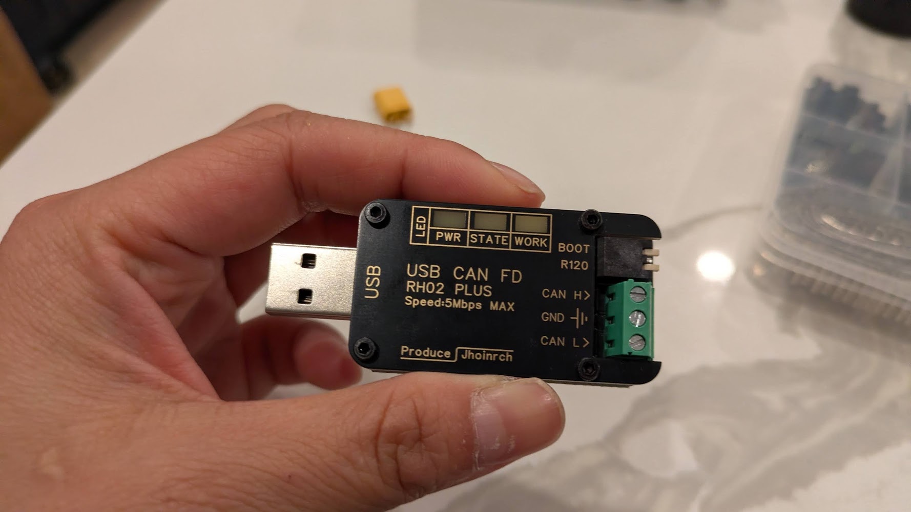
[6] Iif you’re fancy you can terminate the XT30(2+2) data wire in wire ferrules with a crimper, then they fit nicely into the usb can headers)
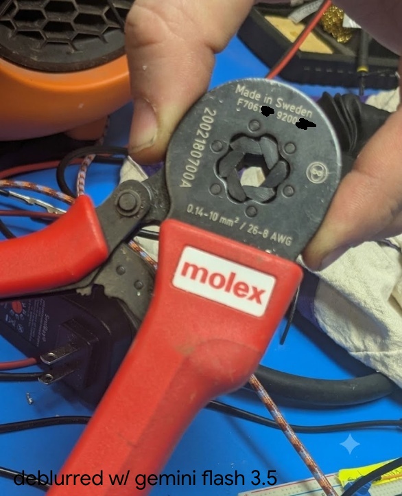
(the bad focus annoyed me so I asked gemini to deblur, but I censored the hallucinated serial number)
If you’re excited to read more about ferrule crimpers, see this post.
[4] The confusing CAN documnt: e.g. ID(7) means device id register is at address 7 (and here it defaults to 001), not the ID is 7. Also — the English version of the CAN protocol document says “ByteDance” everywhere, when it just means “byte”. (ByteDance wrote Tiktok, in case the name sounds familiar). So it’s quite confusing to read… T__T
Learning to Read
anyway so what do all these mysterious numbers mean? let’s dive in
As per the docs, “all multi-byte register content transmissions use little-endian byte order , i.e., the low-order byte first and the high-order byte last”.
MIT Protocol (not MIT controller)
The MIT protocol is a spec for how bytes are laid out on the CAN bus, (and is separate from MIT mode/MIT controller, which is the torque impedance type of controls). The protocol runs over CAN bus and uses 11-bit frames and the message type is determined by length, i.e. 1 byte for ping and status, 3 for reads, 7 for writes, and 8 for commands.
Current Location
So we know that we want to send a 3 byte message.
We then come to the SIAR motor table.
Memory Address
Function
Bytes
DEC
HEX
MODBUS ADDR
552
228
40277
Current Location
4
We also see from the CAN Communication Control Protocol v2, under “Read Register”.
DATA0
DATA1
DATA2
Address (L)
Address (H)
Len
Thus taking
001#280204
We can parse that into the bytes, 28-02-04, then flip since we’re in little endian, so 0x0228, and then the final is 4.
Type of returned position
So we expect to read 4 bytes — in other words the a 32bit value for the position. In the provided example python file we see:
PRESENT_POSITION = 0x228
pos_raw_bytes = motor_comm.read_register(motor_id, PRESENT_POSITION, 4)
if pos_raw_bytes and len(pos_raw_bytes) == 4:
    pos_raw = struct.unpack('<i', pos_raw_bytes)[0]
so the < specifies little endian, then the lowercase i specifies a signed int.
Parsing the position
Again from the demo python code,
RAD_TO_SIGNAL = 2607.5946
This is equivalent to
(2^14)/(2*pi) = 16384 pulses / 2π radians ~= 2607
That is, an encoder that has 14-bit resolution across one revolution (2*pi). So we have 16384 pulses per revolution, and a single pulse is then about 0.02 degrees of revolution. (To verify: this is probably the position of the motor stator not of the output shaft (since there’s a planetary gearbox I think), then there’s a further translation to the position of the gripper jaws).
I didn’t mean this to come across so tutorial-like. The story of the post was meant to be a bit more … here’s the bugs I ran into. A short list.
Bug: I could see from candump that I was sending out pings, but not getting responses
Debug: I hadn’t turned on power to the motor, only plugged in the USB CAM heh. classic.
Bug: The motor would accept pings, torque on, move successfully, then I’d send it a torque off command, and then when I tried to send pings or torque ons, it stopped responding.
Debug: Turned out, I usually turned the gripper off to reposition the motor (since I only cannot go to a + position, not a – position, and I hadn’t rezerod), and when I moved the gripper too fast by hand, presumably the back current going into the motor driver would cause a fault state in the CAN.
This was particularly annoying since I’d have to unplug and replug in the CAN and type in like 5 commands to get back to the same state, since I haven’t set up persistent naming of the device it would increment from ttyACM9 to ttyACM10 etc.
Bug: I knew zeroing command was correct since I’d used it before, but then the motor would not zero and show sudden movement.
Debug: If I looked more closely the motor was sending “00” in response, saying the write had not happened. If I read the docs this is because the register is in EEPROM (persists across reboot) and writes are only during torque off state).
# vi /etc/udev/rules.d/70-can-persistent.rules [5]
SUBSYSTEM=="net", ACTION=="add", KERNEL=="can*", ATTRS{serial}=="YOUR_SERIAL_HERE", NAME="can0

# Then reload
sudo udevadm control --reload-rules
The values can come from running dmesg | tail —
[ 2029.193842] usb 2-2: new full-speed USB device number 13 using xhci_hcd
[ 2029.322042] usb 2-2: New USB device found, idVendor=16d0, idProduct=117e, bcdDevice= 2.00
[ 2029.322060] usb 2-2: New USB device strings: Mfr=1, Product=2, SerialNumber=3
[ 2029.322067] usb 2-2: Product: CANable2 b158aa7 github.com/normaldotcom/canable2.git
[ 2029.322072] usb 2-2: Manufacturer: Openlight Labs
[ 2029.322077] usb 2-2: SerialNumber: 207635634E45
[ 2029.326088] cdc_acm 2-2:1.0: ttyACM2: USB ACM device
Notes
[5] (70 denotes the rough order/priority for udev, the (l)inux device manager to process after the device is plugged in)
Of note, maybe I want more grippers, there is actually an open-source version of a similar gripper mechanism, made to fit around a DaMiao branded gripper. https://wiki.seeedstudio.com/dm_gripper/
next steps
zzz next steps: actually mounting this the UR5, which requires some 3d printing and some cabling.
the end, but i just remembered the other update:
zzzz.
i was supposed to make a cool robot demo with software skills, but i’m still stuck in hardware land right now. but i’m having a lot of fun figuring things out. i find it easy to vortex people the people around me into enthusiasm about real life robots since well, they’re a bunch of roboticists too — don’t quite have the same with software / deep learning yet. but yea!
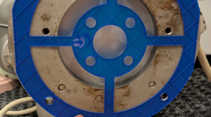
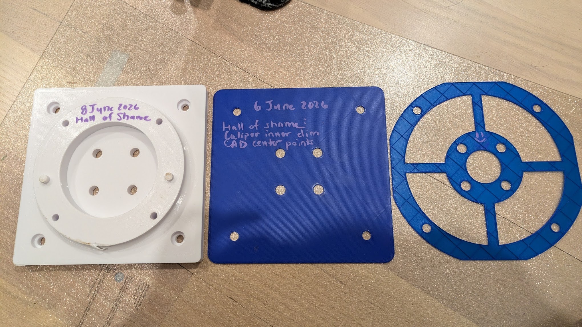
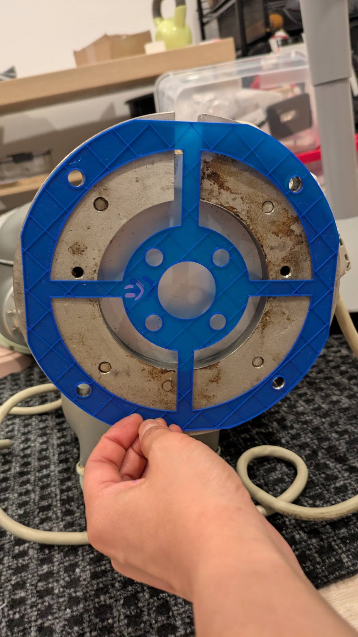
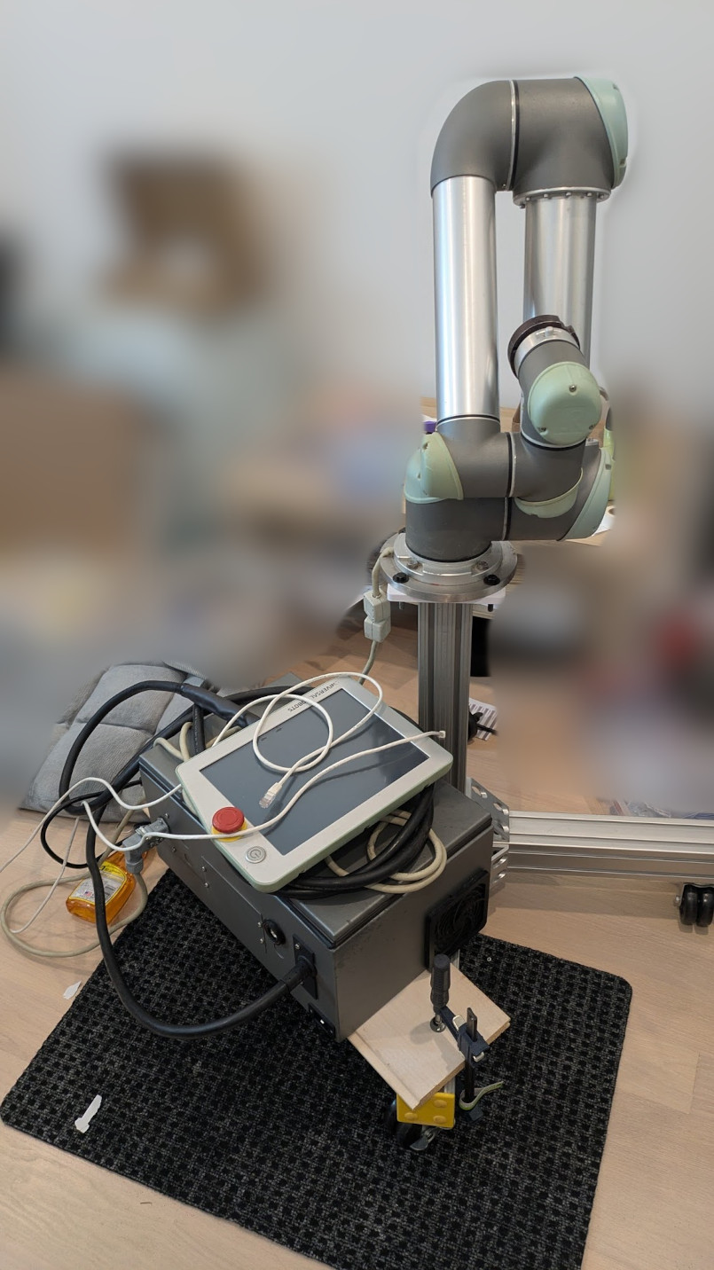
Dane helped source a ton of 80-20 to make a nice wheeled mount for the UR5 (a really nice one tbh) so it doesn’t take over the entire living room all the time. Then we needed to actually attach the arm to the base. I remember around miters we would sometimes hang up mistakes as a funny sort of hall-of-shame. So here’s my pic. I did a 20 hr print (dat 70% infill 10 wall loops yo) that turned out to have indexing issues. Then I was like “heck it we’ll do the simplest possible mount”, dropped the indexing pins, checked the convenient ur5 base had room for the socket cap heads, and printed a … flat block with 8 holes in it. Hey. I’m far from a shop and far from free aluminum blocks, don’t have a saw, and just needed the robot off the floor for a bit (couchsurfer woo). I spent an hour printing the middle blue one, and then realized I’d measured to the inside with calipers then spec’d to the centers with CAD.The next one I was a bit smarter and printed it with no top wall, extrude cuts, and it printed in ~17 minutes. Hold it up to the robot arm:
Yay it checks out! Here’s my 3d printed block attached to the 80-20 lol. I think as a fresh grad I would have felt bad about it. Now I’m years out of my PhD (?!), feel less like I need to prove anything to anyone (i can just point to other stuff I’ve done), and don’t care so long as it gets the job done and I can move on to what I want to work on.
And now mounted. when the robot arm cracks the 3d print, flings itself off of the base, and sends me to the ER, you can tell me “I told you so”