Category Archives: Hardware

hi 2016 (2 servo drawing robot arm, tripod gait 12 servo hexapod, visit to NASA, quadcopter tuning, etc.)

hm, haven’t updated in a while.

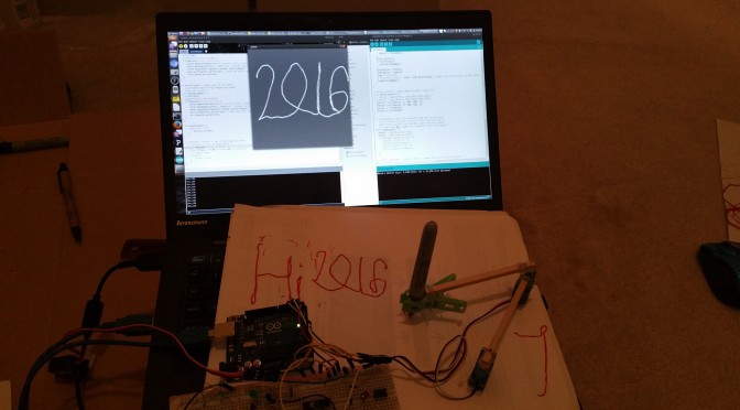
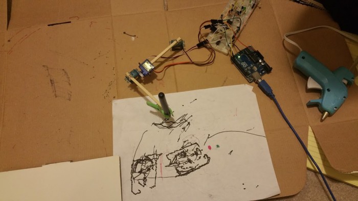
i built a lot of robots with parents over the winter break. i built a robot arm and refreshed on inverse kinematics; more specifically, make sure your servos are rotating as you expect: IK goes counterclockwise since angles increase that way, but your servos may increasing in a clockwise direction… a simple map(theta, 0, 180, 180, 0) will fix your problem if you catch it.

2016-01-01

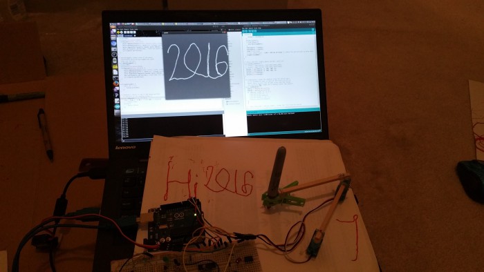
processing takes in x,y coordinates drawn on the screen and spits them out to arduino over serial, which does the inverse kinematics and spits out the theta values to the servo

https://github.com/NarwhalEdu/CopyCat/blob/master/Code/basicsIK/basicsIK.ino

or for the one where it draws what you draw on the screen, https://gist.github.com/nouyang/b312b9ea5c67baa0c914

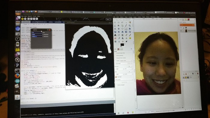
also tried to face.

it does not face well, in part i have derpy three year old code

face3

this processing code takes a lot of processing libraries. thresholds image, performs canny edge detection, then a walking algorithm (look at each black pixel by scanning image in x and y, see if neighbors are black as well, then walk along that pixel) to turn the edges into vectors. then output to robot, but robot is limited in resolution (arduino servo library) and cheap hobby servo overshoot.

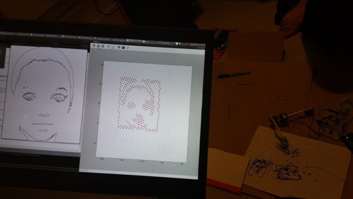
below you can see preview in python.  (basic code, I basically copied the output from processing into a text file and  added some python code to that to plot the values)

is to check image is within the working envelope of the arm. IK is fixed with arm “up”.

face2

faceservo

problem of walking algorithm: adds a box around the image. irritating. need to rewrite code. looking into open cv.

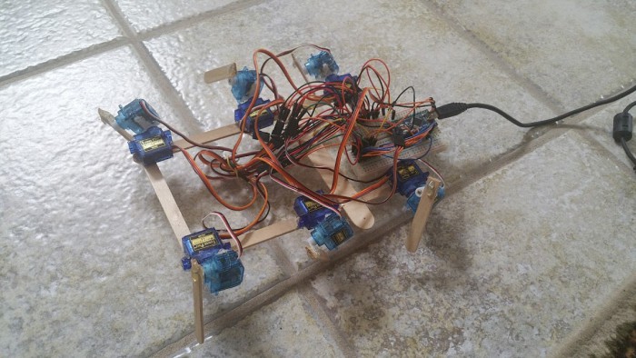
i also rehashed my hexapod project with 12 servos and popsicle sticks

hexapod

basically this https://github.com/nouyang/18-servo-hexapod/blob/master/arduino_may13_2011.pde

but modified to work with the servo configuration on the rectangular robot, and added code to allow you to step through the gait with “j” and “k”: https://gist.github.com/nouyang/d9b6474e3ee412b9b05b

need to implement the other gaits; also, this moves so smoothly, envious, but they have lasercutter :3

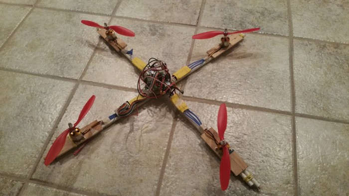
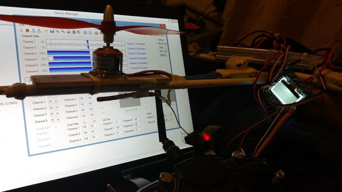
worked on quad, now stuck at calibration stage 😡 because i have not built quad before, i could not push through this in a day or two unlike the drawing arm and hexapod.

quad


made from a sad clothes drying rack we took apart


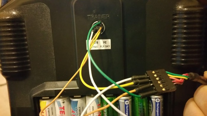
transmittercable

we couldn’t find the original cable for the transmitter, so we connected the ports up with a FTDI -> USB cable as per http://psychoul.com/electronics/how-to-make-your-own-usb-cable-for-hk-t6a-calibration

zero

used http://www.sgr.info/usbradio/download.htm and calibrated my servos to zero… took a while to realize it *can* and *should* read the current values, guess my wires were loose, but the values because a lot easier to input. used the kk2 screen to fix some controls that were reversed from what the kk2 expected (left = left and not right, etc.). zeroed all the values on the kk2. turns out (minus the flipping controls) I could zero just as well on using the trim knobs on the controller itself.

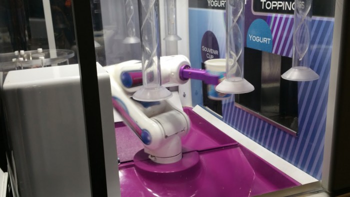
went to visit NASA space museum in houston. they had little robot that made and served you froyo. adorable.

nasaicecream

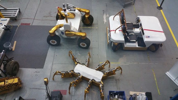
also, some regal looking hexapods in the actual NASA workplace.


nasarobot

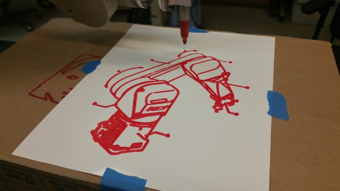
at MITERS I got a robot arm working with lots of help from MITERS / London Hackerspace / john from BUILDS. For robot arm competition. http://robotart.org/

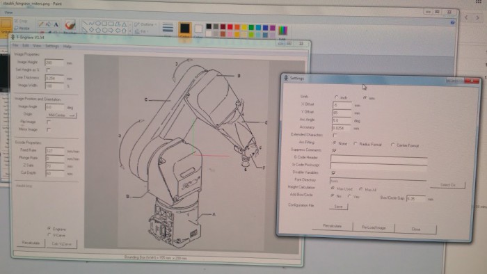
i’m now robot art-ing. here is using Fengrave on a black and white image with appropriate offsets to produce gcode (well, limited to G0 and G1 commands)

fengrave

robotdrawing

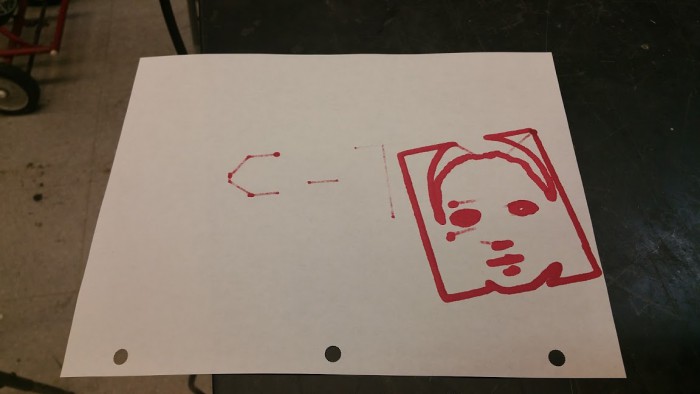
face code still derp. (streaks are because i wrote gcode translator, and it goes to x,y,z position instead of x,y and then z). too many x,y points. draws slowly.

face

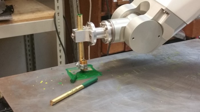
michael made crayon extruder (=metal tube + power resistor) and also pen mount. crayons = hard to control flow rate. started making square, then pooped out a lot of melted crayon. alas.

crayonextrusion

learned a lot of patience dealing with old manuals, 20 year old operating systems / controllers. main issue turned out to be a dumb calibration assumption (robot had arrows; should have ignored them and used indentations instead).

https://github.com/miters/gdmux gcode -> V+

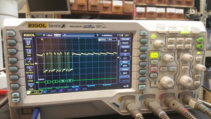
also, i learned about oscilloscope rs232 decoder! had to invert to get it working properly (zeros are high in rs232?). scope ground, tx line. bam, now you can check whether you are actually transmitting all the carriage return and line feeds you need…

2016-01-13

currently: reading up on image processing. openCV. http://web.cs.ucdavis.edu/~ma/SIGGRAPH02/course23/notes/S02c23_3.pdf

terse update. more details available if questions exist.

many thanks to my parents for being excited and not jaded

DIY Menstrual Cups & Hack4Fem

Background on Menstrual Cups

I’ve been throwing around the idea of customized or instrumented menstrual cups for a while.

Menstrual cups, typically made of medical-grade silicone, are cups that catch the blood flowing out of the cervix and typically only need to be emptied twice a day. They are flexible so you fold them and they open on insertion. They exist in collapsible, ball-valve, and other forms.

For why I love them (well, I actually switched to tampons first):

so recently I started regularly using tampons, they are amazinnnnggg

seriously
every month my sleep schedule would get massively disrupted, because I slept uneasily, sometimes even in an upright sitting position, ready to jump awake when blood inevitably started to go everywhere, and also I’d have to wash my sheets and multiple sets of underwear / pants each month, often by hand
or i’d store pads in my bookbag and a month later when I needed them again, they’d be full of resistors and other bookbag filth, since the pad packaging isn’t really watertight

Some of my friends like the concept of menstrual cups, but have various problems with removal and leakage. I speculate that custom cups could help, although more analysis is needed to determine the cause and the variation. Hence this project.

I also really like the idea of an citizen science project measuring variation in periods. Other people claim a Diva cup is supposed to hold half your period’s worth of blood — I definitely bleed at least four cup-fulls during my period, so I wonder if my bleeding is heavy. If lots of people contributed data, we could see whether it varied by ethnicity, age, body weight, etc. It would be a ton of fun!

I was beaten to the punch on instrumented cups, but I think there is still room for improvement (or at least an open-hardware version).

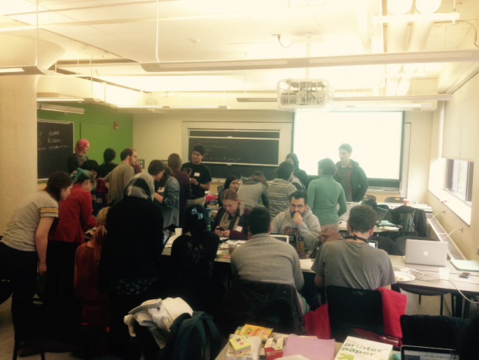
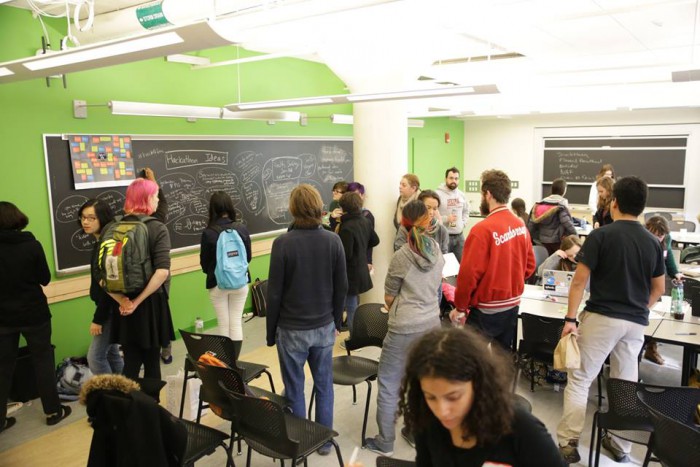
This past Saturday I ran a hackathon for feminism (website here).

2015-11-14

It went really well, and I’ll blog about it in another post shortly — this one’s focused on menstrual cups 🙂

hackathon

pre-hackathon

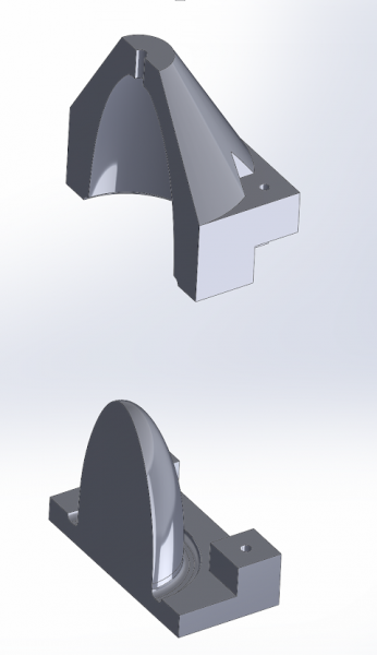
Before the hackathon, John and I made menstrual cup molds and cast menstrual cups. We modeled it in Solidworks, then intersected it with a rectangular prism and split the prism in half. This created a two-part mold with a cavity in-between the size and shape of the menstrual cup. The Solidworks 2015 files are available here and are CC-BY-SA (c) John Aleman.

model

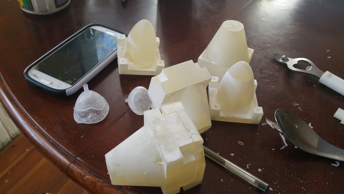
We then printed these out on a Stratasys printer, melted the wax support material off in the toaster oven, cleaned off with isoproprly alcohol, and had our molds.

2015-11-12

I first tested it at home with John’s help. We used Smooth-On’s SORTA-Clear Translucent Silicone Rubber, shore 37, since it cures in 4 hours instead of 24 hours. This is food safe and I think body-safe — I would call Reynold’s Advanced Materials to double-check before actually using one of these cups.

Turns out this material was really difficult to work with… it was the consistency of viscous snot.  No pictures pre-hackathon since the silicone is messy. I sure had a difficult time separating the molds. And it turned out we hadn’t even filled the molds for two of them!

incomplete-molds

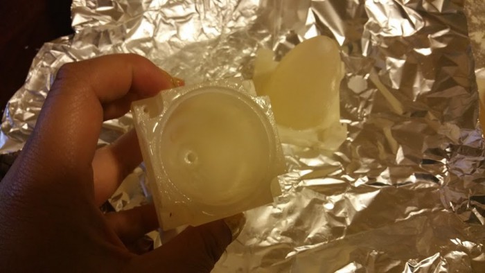
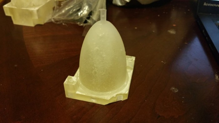
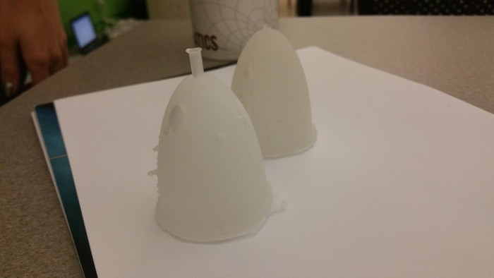
Eventually some careful prying by my friend Nadya, we opened the final mold to find a menstrual cup inside!

mcup-mold

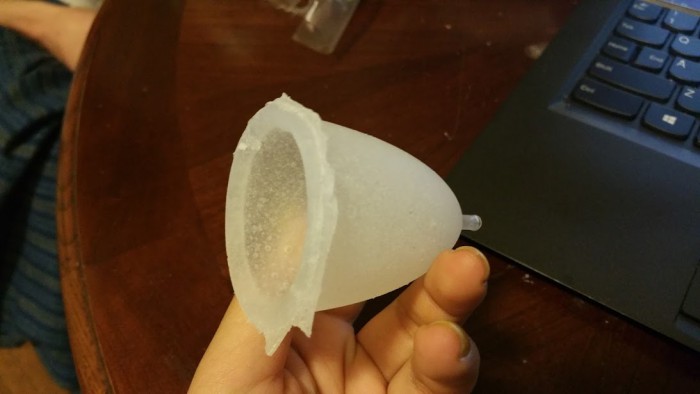
mcup

It had a lot of bubbles — would have benefited from 2-3 minutes in a vacuum. Unfortunate, since there doesn’t seem to be a cheap hobbyist vacuum solution. It was also slightly tacky, so either something in the 3d print is inhibiting cure or we didn’t mix well enough.

hackathon hands-on workshop

hackathon-molds

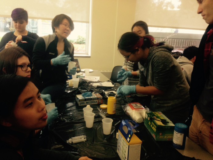
At the hackathon, we used syringes to eject into the molds until it came out the sides, and also just poured it into the bottom half of the mold and squeezed the top half on top to guarantee the mold was filled. We also all got pretty excited about the idea of glittery menstrual cups! 🙂 Sadly I didn’t have glitter on hand.

twocups


At the end of the hackathon we managed to demold one. This one  also had a giant bubble and many little bubbles, and was also tacky after the full four hours of cure time. We mixed this one much better, so I’m starting to think something is inhibiting cure, or perhaps the place we left them was too chilly.

next up

I definitely need a better mold design, and I need to figure out why the silicone is not curing properly. I also need to figure out a way around the bubble issue.

I also wonder how to analyze and determine why menstrual cups are failing (when they are hard to retrieve or leak). I also wonder, if fit is part of the problem, how you could easily take a measurement(s) to customize menstrual cups to each person.

And of course, I want to build the open science project! 🙂 Maybe instead of having each person build their own cup, I could at least start a form going and collect data…

Organizing an solid modelling CAD reading group (toward FOSS CAD)

I’m starting a new reading group!

The idea is to get a good background on parametric solid modelling CAD (think solidworks, proE, openSCAD).

(to be clear, NOT how to use the tools, but how to write new ones or contribute to FOSS implementations).

I think the first group meeting would simply be an overview of existing approaches and the pros/cons of existing FOSS CAD software (as well as introductions to each other).

Proposed time is 6pm EST Sundays over google hangouts (and possibly simultaneously in person in Camberville, MA), totally open to other times.

Sign up here: FORM