
been spending money lately
mixed feelings ’bout my consumerism of things i feel like i might only use once or twice but i tell myself it’s research 😛
gamibot
based on
http://www.howtoons.com/?p=3484
these are super cool because you use a business card instead of a toothbrush, i have twenty extra business cards but not twenty toothbrushes and it’d be a shame to buy new toothbrushes just to chop off their heads
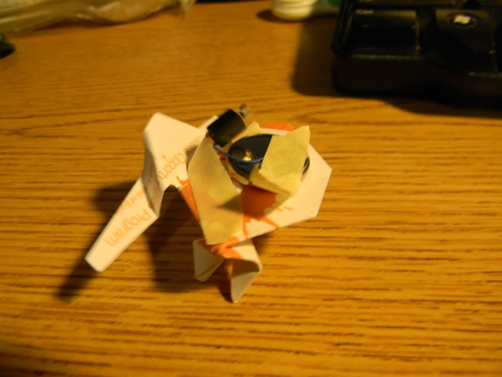
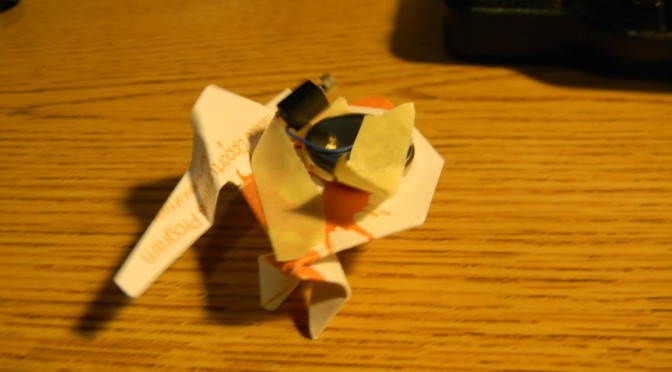
all it needs is a business card, tape, a pager motor, and a battery 🙂 so cute.
pager motor placement affect movement a lot, e.g. I changed the placement a bit and this one moves faster and more forwards than sideways
anyway, to start this story off, i am co-teaching a few lessons in 4th grade for my d-lab education class. and last year when we went to China, +Cathy Wu bought a bunch of pager motors in preparation for making swarmbots. I then bought a couple dozen off of her this year in preparation for bristlebots but then realized I needed to solder leads to them. The type she bought is to the right in this picture:
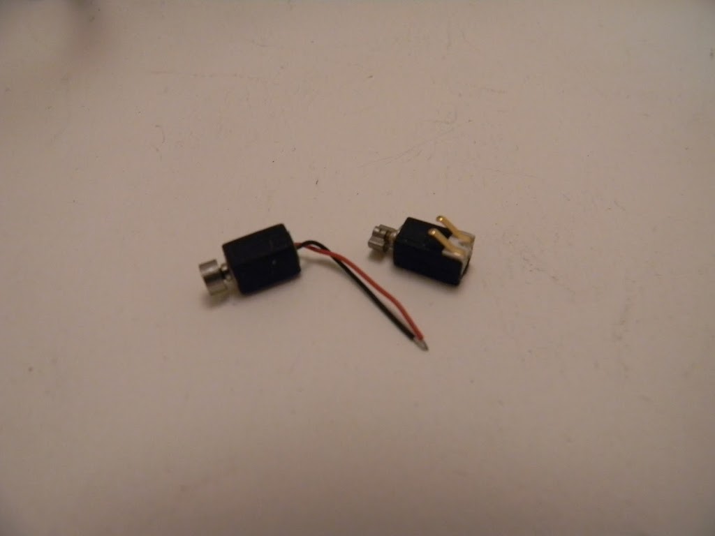
I tried soldering wires onto the tiny motors (they are about 1cm long) and promptly desoldered the metal leads from motor. Well, crap.
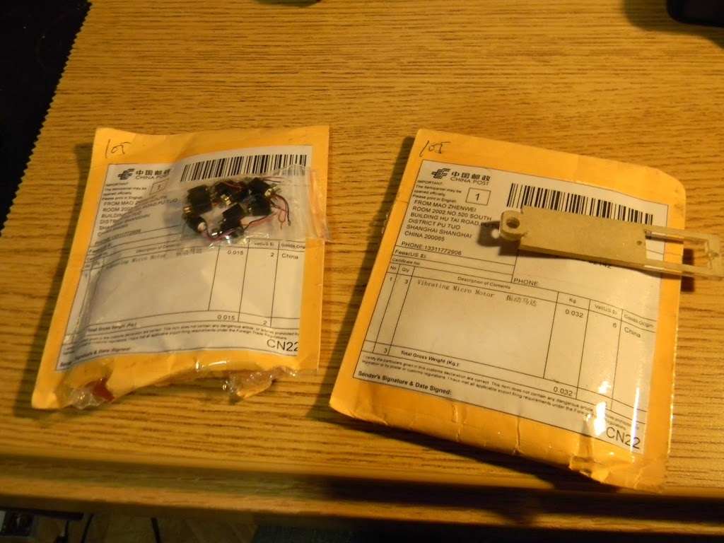
Anyway, I ordered some pager motors off of ebay for 84 cents each and they arrived eight days from ordering from China. I expected it to take three weeks so it was a pleasant surprise. (Well, I bought from two sellers and the other packaged arrived in 10 days).
 |
| that’s a bag of 30 motors! i could fit them in wallet. they come with pre-formatted messages. I wonder if these two are actually the same seller. |
I found better “hard hardware” streets in Shanghai TBH, & don’t remember seeing tons of motors in SZ.
Yup, I think you are right. SEG looks like the place to go for electronics, but Shanghai had way more mechanical stuff. It was a fun visit, though!
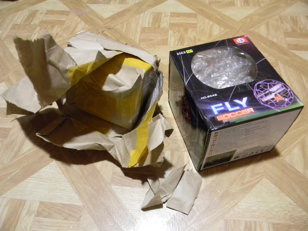
soccerballcopeter
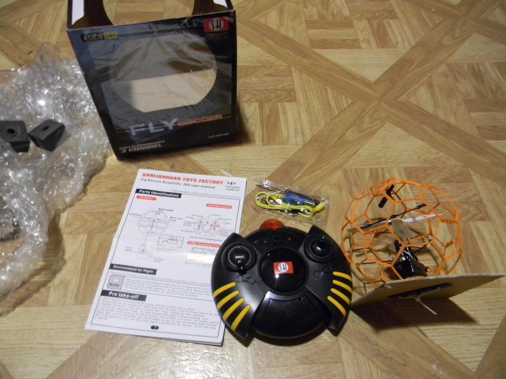
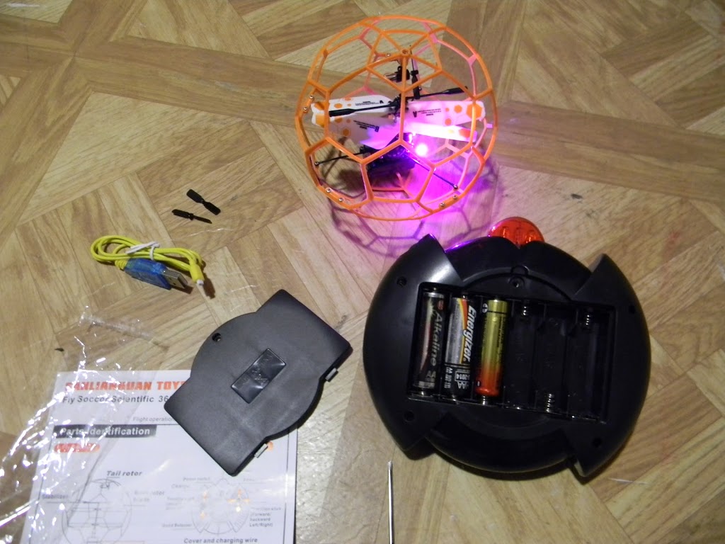
In other news I am playing poking at copters a bit for the lulz. (I have been spending more money ever since making decent money at fitbit last summer… no regrets! i think)
“Pro 6042 Flying Ball Scientific 3CH R/C UFO Remote Control Gyro LED Helicopter”
22.91 + 1.6 shipping
bought 3/26 arrived 4/4 (nine days)
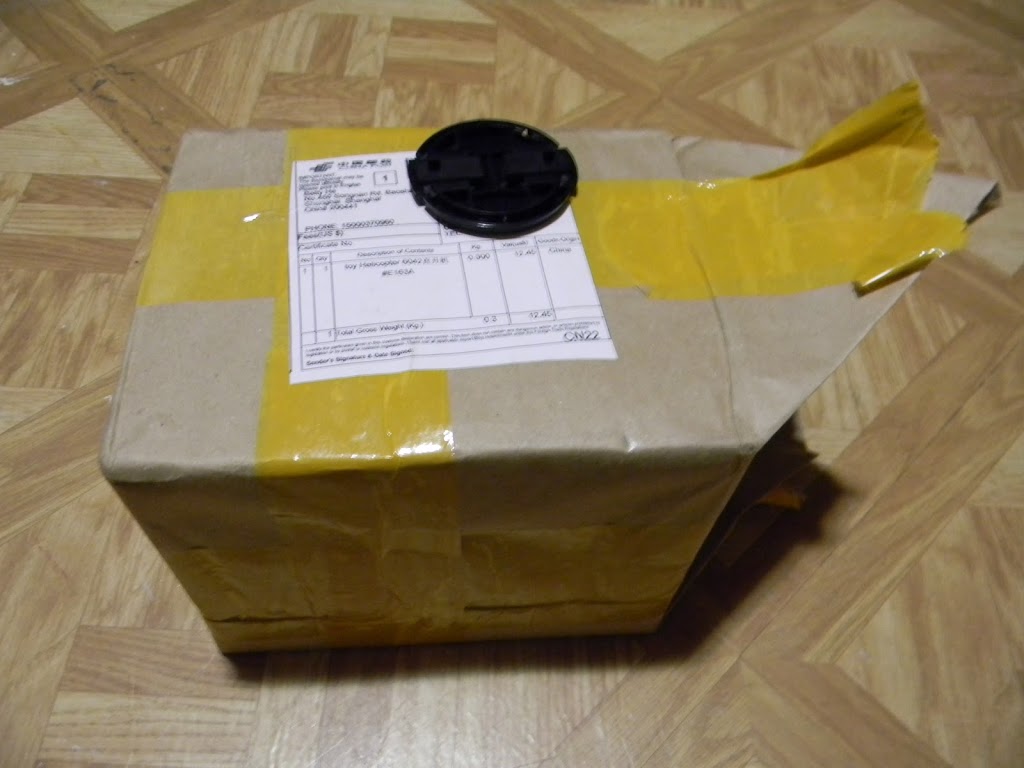

things from ebay/china
Also, can we just take a moment and reflect how amazing it is that I can get a functioning flying thing complete with wireless control shipping to be from China for a total of $25 USD? That’s like 1.5 arduinos without batteries or anything at all. Mass manufacturing is awesome.