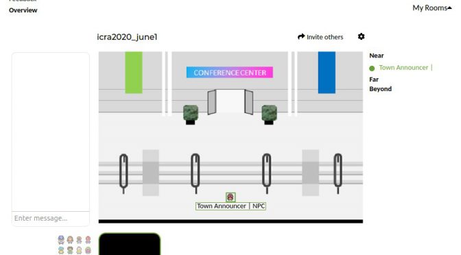
Made a quick NPC announcer for this virtual pokemon style gathering tech (aka Online Town)

Online Town was used for a previous conference, ICLR, where people even “went to the beach” (there’s several environments, I chose the conference hall one).
ICLR Town: Pokemon-esque environment to wander around and bump into people, which syncs almost seamlessly with video-chatting capabilities. — maithra_raghu
However there is no chat history, and no way to set a description or announcements. In order to do so, Ondrej Biza suggested I actually just have a repeating audio announcement character: the Town Announcer.
After some googling, I quickly whipped together a set of bash scripts to do so. This is is Ubuntu 18.04.
1. Create recording of the announcement
I used `festival`, since I already had that installed for my terminal timer (blinks the terminal red, plays a loud sound, and speaks “n minutes are up”).
sudo apt install festival
text2wave onlinetown.txt | lame - text.mp3
Inside the text file I had
$ vi onlinetown.txt

Welcome! The next scheduled event is: Happy Hour at 5pm Eastern. Again that
is at 5pm Eastern. Move away
to stop hearing this voiceover. To add to this voiceover email me at a b c at m i t dot edu
(Side note: Somehow festival is really bad at pronouncing email, oh well).
2. Create “virtual microphone”
I can then select this as my mic input for the videoconference
As per sebpiq on stackoverflow
pactl load-module module-pipe-source source_name=virtmic file=/tmp/virtmic format=s16le rate=16000 channels=1
3. Play speed recording over virtual mic
As per sebpiq on stackoverflow
ffmpeg -re -i text.mp3 -f s16le -ar 16000 -ac 1 - > /tmp/virtmic
4. Create bash script to continuously do so
$ vi loop_mic.sh

#!/bin/bash
while true
do
echo "Press [CTRL+C] to stop.."
ffmpeg -re -i text.mp3 -f s16le -ar 16000 -ac 1 - > /tmp/virtmic
sleep 0.5
done
5. Run it
chmod +x loop_mic.sh
sh loop_mic.sh
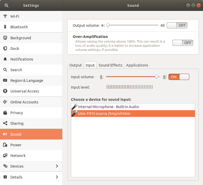
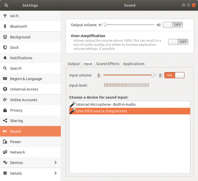
Check that it’s in the settings
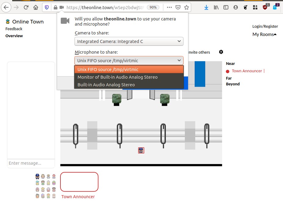
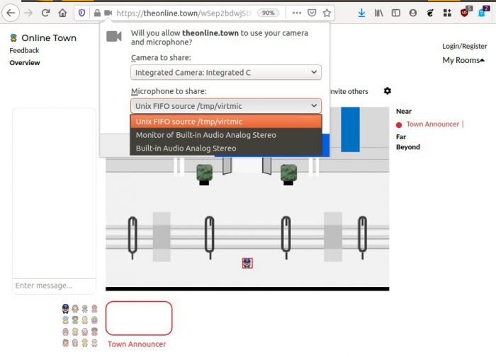
Then open online.town, and when it asks for which microphone input to select, select the Unix FIFO.
To check that it’s all working, I joined from another computer & could hear the announcer. Sometimes it does seem like I can’t hear the announcer when joining, but I can’t reliably reproduce it.
Another sanity check is to go back to Sound settings and check that the “input level” bars are going up and down.
Appendix
I did try speeding up the audio, but it did introduce new audio artifacts (squeaks). If you want to do so, add a setting when generating the mp3. Below it speeds up to 2x.
text2wave -eval "(Parameter.set 'Duration_Stretch 0.5)" onlinetown.txt -o text.mp3
( I also tried speeding it up in the `ffmpeg` command, it sounded horrible).
Better text to speech
This was a pain… ! Not sure why. Very confusing instructions.
Helped in part As per. https://levelup.gitconnected.com/installing-mozilla-tts-on-a-raspberry-pi-4-e6af16459ab9
These are final records of what worked.
 2022  apt-get install -y espeak libsndfile1 python3-venv
 0000 python3 -m venv env
 0000 source env/bin/activate
 2029  pip3 install -U pip setuptools wheel
 2050  pip install https://github.com/reuben/TTS/releases/download/ljspeech-fwd-attn-pwgan/TTS-0.0.1+92aea2a-py3-none-any.whl
 2001 git clone git@github.com:mozilla/TTS.git
 0000 cd TTS
 2053 pip3 install packaging
 2052 python -m TTS.server.server
 0000 firefox localhost:5002
# FAILS unless inside TTS git folder!
Traceback from failure:
# FAILURE CASE
$ python -m TTS.server.server
> Loading TTS model ...
| > model config: None
| > checkpoint file: None
Traceback (most recent call last):
File "/usr/lib/python3.6/runpy.py", line 193, in _run_module_as_main
"__main__", mod_spec)
File "/usr/lib/python3.6/runpy.py", line 85, in _run_code
exec(code, run_globals)
File "/home/chai/projects/TTS/server/server.py", line 62, in <module>
synthesizer = Synthesizer(args)
File "/home/chai/projects/TTS/server/synthesizer.py", line 36, in __init__
self.config.use_cuda)
File "/home/chai/projects/TTS/server/synthesizer.py", line 52, in load_tts
self.tts_config = load_config(tts_config)
File "/home/chai/projects/TTS/utils/io.py", line 16, in load_config
with open(config_path, "r") as f:
TypeError: expected str, bytes or os.PathLike object, not NoneType
Some other commands I tried (didn’t work)
https://github.com/mozilla/TTS/wiki/Released-Models#simple-packaging---self-contained-package-that-runs-an-http-api-for-a-pre-trained-tts-model

sudo apt-get install -y espeak libsndfile1 python3-venv
python3 -m venv env
source env/bin/activate && which python3
pip install -U https//example.com/url/to/python/package.whl
pip3 install -U pip setuptools wheel
$ python -m TTS.server.server --help
It will say synthesizing, After a minute or two it will finish and start playing the audio. Right click and “save audio”
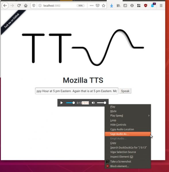
Output is a wav file.
What successful TTS.server.server looks like:
(env) 15:53:25 chai@W530:~/projects/TTS (master %)$ python -m TTS.server.server
/home/chai/projects/env/lib/python3.6/site-packages/librosa/util/decorators.py:9: NumbaDeprecationWarning: An import was requested from a module that has moved location.
Import of 'jit' requested from: 'numba.decorators', please update to use 'numba.core.decorators' or pin to Numba version 0.48.0. This alias will not be present in Numba version 0.50.0.
  from numba.decorators import jit as optional_jit
 > Loading TTS model ...
 | > model config:  /home/chai/projects/env/lib/python3.6/site-packages/TTS/server/model/tts/config.json
 | > checkpoint file:  /home/chai/projects/env/lib/python3.6/site-packages/TTS/server/model/tts/checkpoint.pth.tar
 > Setting up Audio Processor...
 | > sample_rate:22050
 | > num_mels:80
 | > min_level_db:-100
 | > frame_shift_ms:12.5
 | > frame_length_ms:50
 | > ref_level_db:20
 | > num_freq:1025
 | > power:1.5
 | > preemphasis:0.98
 | > griffin_lim_iters:60
 | > signal_norm:True
 | > symmetric_norm:True
 | > mel_fmin:0
 | > mel_fmax:8000.0
 | > max_norm:4.0
 | > clip_norm:True
 | > do_trim_silence:True
 | > trim_db:60
 | > sound_norm:False
 | > n_fft:2048
 | > hop_length:275
 | > win_length:1100
 > Using model: Tacotron2
 > Loading PWGAN model ...
 | > model config:  /home/chai/projects/env/lib/python3.6/site-packages/TTS/server/model/pwgan/config.yml
 | > model file:  /home/chai/projects/env/lib/python3.6/site-packages/TTS/server/model/pwgan/checkpoint.pkl
 > Setting up Audio Processor...
 | > sample_rate:22050
 | > num_mels:80
 | > min_level_db:-100
 | > frame_shift_ms:12.5
 | > frame_length_ms:50
 | > ref_level_db:20
 | > num_freq:1025
 | > power:None
 | > preemphasis:0.98
 | > griffin_lim_iters:None
 | > signal_norm:True
 | > symmetric_norm:True
 | > mel_fmin:0
 | > mel_fmax:8000.0
 | > max_norm:4.0
 | > clip_norm:True
 | > do_trim_silence:True
 | > trim_db:60
 | > sound_norm:False
 | > n_fft:2048
 | > hop_length:275
 | > win_length:1100
 * Serving Flask app "server" (lazy loading)
 * Environment: production
   WARNING: This is a development server. Do not use it in a production deployment.
   Use a production WSGI server instead.
 * Debug mode: off
[INFO]  * Running on http://0.0.0.0:5002/ (Press CTRL+C to quit)
 > Model input: Welcome! The next scheduled event is: Happy Hour at 5pm Eastern. Again that is at 5pm Eastern. Move away to stop hearing this voiceover.
['Welcome!', 'The next scheduled event is: Happy Hour at 5pm Eastern.', 'Again that is at 5pm Eastern.', 'Move away to stop hearing this voiceover.']
[INFO] 127.0.0.1 - - [01/Jun/2020 15:54:03] "GET /api/tts?text=Welcome!%20The%20next%20scheduled%20event%20is%3A%20Happy%20Hour%20at%205pm%20Eastern.%20Again%20that%20is%20at%205pm%20Eastern.%20Move%20away%20to%20stop%20hearing%20this%20voiceover. HTTP/1.1" 200 -
Hurray. ! The output sounds much nicer.
Note:
Undo with
pactl unload-module module-pipe-source