Category Archives: Hardware

Dreaming of Dancing Hexapods (2.007 Reflection and Learning)

This semester, I’ve been on-off productive in 2.007, where I’ve been working on a hexapod. The original goal was to build a dancing hexapod. I think this was entirely reasonable if I’d been a bit more time-saavy in life, instead of living life from one deadline to the next. Ah well 🙂

(This post is in response to my homework assignment).
Evolution of a Hexapod:

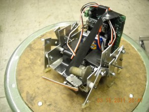
Hexalinkagepod. Mini-hexapod (my “simple-bot” exercise). Two servo linkage-hexapod based off of the Parallax BoeBot Hexapod.
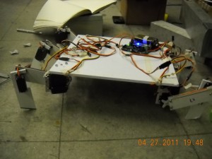
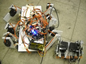
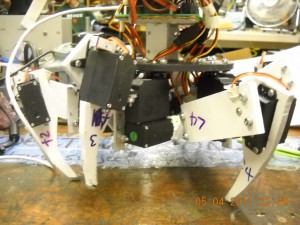
Hexablockapod. First iteration, 18 servo hexapod. Wide body (full sheet of ABS plastic). Doesn’t walk well at all.
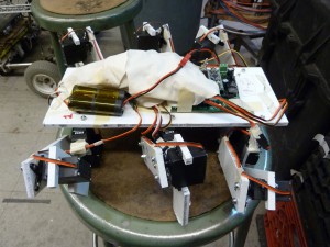
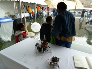
Hexablockapod v2. 2nd iteration, 1/3 sheet ABS plastic. Oh, and mini-hexapod for comparison.
Wires hidden with some cloth (4/30/11)
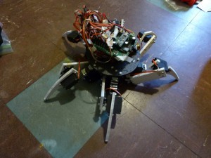
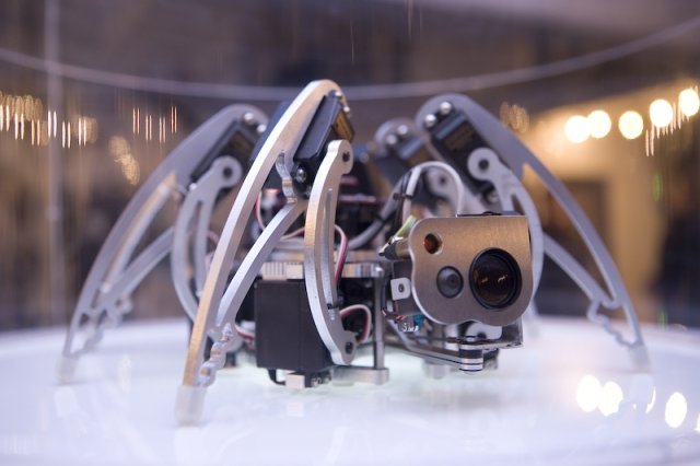
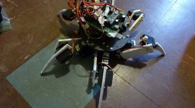
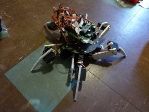
Hexaringapod. Current iteration. ~6” radius body (black ABS plastic). Used vertical bandsaw to add curvature to & reduce weight of outermost segments (tibia). Shortened femurs. (5/6/2011)
0. Hexapod basics
Hexapod — “six-footed”. In this case, a six-legged walking robot; in nature studies, hexapoda = a group of arthropods including the insects. Also refers to a type of robotics platform called the Stewart platform. (this turns up often in google image searches).
There exist a bewildering array of hexapods, from one motor seventy-foot diameter hexapods to three servo one-inch diameter hexapods to wooden wind-powered beach-walking hexapods to eighteen half-foot diameter dancing hexapods. Square hexapods, pyramidal, circular, CNC hexapods (yes, a hexapod that mills things), the variety is amazing. (todo: add links. Jamie’s spider, strandbeest, pololu hexapod, wikipedia hexapod, linkages).
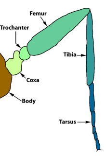
Here, I will focus on 18 servo hexapods at the cost of discussing interesting linkages (Klann, Jensen, etc.). 18-servo hexapods use three servo motors per leg and mimic the insect leg, specifically the coxa, femur, and tibia segments.

There doesn’t appear to be concrete mathematics studying the physics of the insect leg, at least not applied to hexapods. The overuse of servos in 18-servo designs allows for lots of leeway in design, leading to some truly beautiful hexapods. It also allowed me to build one entirely by eye (no CAD), for better or for worse.
this makes me go squeeeeee.
1. Description of the final machine:
My final hexapod has eighteen servos on six legs. It walks, and can accomplish more movements given time to program. The walking gait is a tripod gait, where in theory three legs are on the ground at any given time.
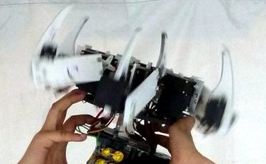
close-up of final machine. Not as objectively squee-worthy as other people’s designs, but I built it all by hand and it’s all my own. <3 
When I started out on the 18-servo hexapod, based on the plethora of designs and a naive belief that my servos could handle anything, I believed that I could “just build” a dancing eighteen-servo hexapod and ignored people’s advice that I CAD my robot before I build it. (Well actually, at first, I had zero belief that I could actually build an 18-servo hexapod nor any idea how to build one. But I really really wanted a dancing hexapod, so it all worked out thanks to the UAs, TAs, professors, shop guys, and the MITERS emailing list. Yay!).
Video of walking (and maybe more?) to come; I took it to Cambridge Mini Maker Faire and a little kid broke one of the servo horns in the first ten minutes, heh (easy to fix). Little kids are epic mechanical design testers.
Yes, little kids should build dancing hexapods too!
2. Some comparisons
I do not know of anyone else in 2.007 who attempted to build a walking robot nor a similar task of dancing. Instead, I will compare my design with some designs from the internet, where I drew my inspiration. I will focus on mechanical design of 18 servo hexapods.
Original inspiration:
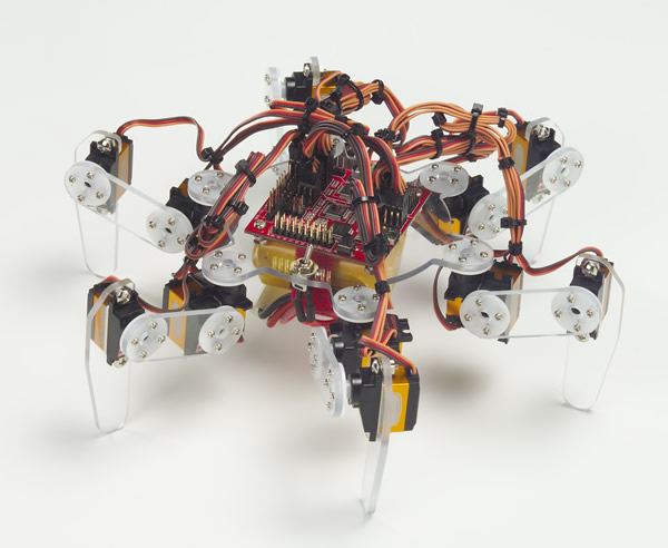
Leg design inspiration:
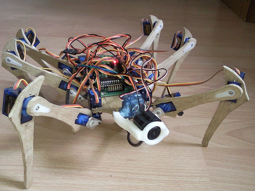
Final body design inspiration:
http://www.youtube.com/watch?v=glNS81Kgk7g
Future gait studies:
Future aesthetic studies:
Future servo torque / weight studies:
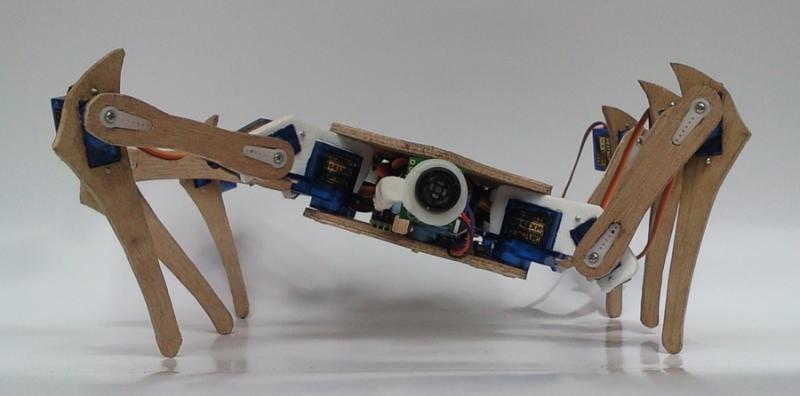
This hexapod uses 1.6 kg*cm servos, with longer leg segments, while I’m using 3.2 kg*cm servos with shorter segments, yet this hexapod has no problems moving around.  Possibly a combination of lighter weight (due to using thin wood instead of 1/8” ABS plastic?) and better mechanical design (e.g. better support for the servos) and better programming (not holding the tibia static, as I am right now).
Principles:
  • Support servo on both sides (add second pivot point, opposite of output shaft). See http://www.lynxmotion.net/viewtopic.php?f=17&t=3133 for ideas. I did not do this on my design, since I was opting for KISS due to my inexperience with building my own robots from scratch.
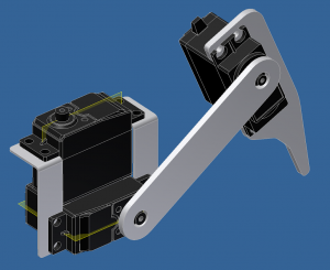
  • Instead of having coxa servo support its own weight in addition to the other two servos (femur and tibia), put it on the body and let it rotate the rest of the leg. See sandwich design:
  • The coxa segment probably needs the least torque (I put my weakest servos on the femur segment)
3. Use of design tools.
Design tools allowed clear images to be found on the internet, which helped me with creating my own design. I made less use of these tools than other people around me, which is acceptable as my next revision of the hexapod will certainly involve Solidworks and Inkscape / Coreldraw.
4. Things I learned: (what I would do differently)
Although I stand by my decision to go ahead and build the robot roughly by eye, since I do not believe that Solidworks would have helped me anticipate issues with servo torque, I definitely intend to use CAD tools in the future.
I think I should have attempted to balance the 2.007 workload better than work on spurts every week or two.
In retrospect, I should have picked the easiest available option for connecting and running all 18 servos and run with it as soon as possible, which would have allowed me to see the problem with the oversize body and weak servos much sooner. I often had issues with decision making, and I am glad that I decided to try cutting the robot in half instead of vacillating for a while.
I had thought that there was no need to consider servo torque since I did not need to decide which servos to buy; however, this was an incorrect philosophy as I could have changed the design.
(I had no intuition at the time for servos and torque, and when I asked around people thought my design seemed reasonable. Next time I will definitely be considering servo torque issues — a bit of research reveals that some dancing hexapods use servos with 2x or 5x the torque of my servos).
Solidworks would probably have helped me with my little hexapod, where the leg lengths where off.
In terms of fabrication, I learned to standardize my nuts and bolts (sticking to only 4-40) and the niceties of working with ABS plastic (fast prototyping changes, such as bandsawing my robot in half and reattaching the legs, could be accomplished painlessly).
Epilogue
In conclusion, I’ve decided to open a business selling dancing hexapod hats.

thanks for the idea, Mr. Finberg!
A build post will come soon (probably after finals in a week).

Hexapod status update: it walks, and it’s no longer blocky

My pet 18 servo hexapod <3

In terms of programming, I’m following the tripod gait (3 legs on the ground at any time, legs in the air move forward while legs on the ground move backward). I’m using the Arduino mini as the microcontroller (brains) (with the 2.007 carrier board to make interfacing with the servos easy). I’m controlling 12 channels (which is the max for the ServoWrite function in the Arduino software library), so twelve of the servos are in pairs (using six Y splitter cables). Thus, if  I named each leg:


front
A   D
B   E
C   F
back

The servos on AC and DF are linked together, while the servos on B and E are controlled independently. Then I only need 12 channels instead of 18: AC (coxa, femur, tibia). DF (coxa, femur, tibia). B  (coxa, femur, tibia). E  (coxa, femur, tibia).

Anyway, in my code, I took 4 “snapshots” (sets of servo positions) of the tripod gait and I’m looping through them. In other words, I’m following http://www.pololu.com/docs/0J42/4. I’m pretending this is a 12 servo hexapod (since this was my KISS code) in that the tibia segments are kept at one position the whole time.

  1. AC, E legs forward. DF, B legs backward.
  2. AC, E legs down. DF, B legs up.
  3. AC, E legs backward. DF, B legs forward.
  4. AC, E legs up. DF, B legs down.

And the actual code I’m using to get it to walk forward:
(also here: https://docs.google.com/document/pub?id=1N9dLEcLXiCvFRI4JRVfJUyylEhZFk4azP8_gsickQv4)

 #include <servo.h>
// Declare constants in degrees for the servos
#define TIBIA 45
#define DELAY 200

// +J, BWD = forward, backward (coxa)
// UP, DOWN = up, down (femur)
#define AC_FWD 105
#define AC_BWD 70
#define AC_UP 92
#define AC_DOWN 125

#define B_FWD 95
#define B_BWD 90

#define DF_FWD 70
#define DF_BWD 105

#define E_FWD 90
#define E_BWD 95

int UP = AC_UP;
int DOWN = AC_DOWN;

Servo E_coxa;
Servo E_femur;
Servo E_tibia;

Servo B_coxa;
Servo B_femur;
Servo B_tibia;

Servo AC_coxa;
Servo AC_femur;
Servo AC_tibia;

Servo DF_coxa;
Servo DF_femur;
Servo DF_tibia;

int pos = 0; // variable to store the servo position

void setup()
{
//Set all pins to output, disable the pullup resistors or something, etc.
digitalWrite(2, OUTPUT);
digitalWrite(3, OUTPUT);
digitalWrite(4, OUTPUT);
digitalWrite(5, OUTPUT);
digitalWrite(6, OUTPUT);
digitalWrite(7, OUTPUT);
digitalWrite(8, OUTPUT);
digitalWrite(9, OUTPUT);
digitalWrite(10, OUTPUT);
digitalWrite(11, OUTPUT);
digitalWrite(12, OUTPUT);
digitalWrite(13, OUTPUT);

pinMode(1, OUTPUT);
pinMode(2, OUTPUT);
pinMode(3, OUTPUT);
pinMode(4, OUTPUT);
pinMode(5, OUTPUT);
pinMode(6, OUTPUT);
pinMode(7, OUTPUT);
pinMode(8, OUTPUT);
pinMode(9, OUTPUT);
pinMode(10, OUTPUT);
pinMode(11, OUTPUT);
pinMode(12, OUTPUT);
pinMode(13, OUTPUT);

E_coxa.attach(2);
E_femur.attach(3);
E_tibia.attach(4);

B_coxa.attach(5);
B_femur.attach(6);
B_tibia.attach(7);

AC_coxa.attach(11);
AC_femur.attach(12);
AC_tibia.attach(13);

DF_coxa.attach(8);
DF_femur.attach(9);
DF_tibia.attach(10);
}

void loop()
{
tibia();
tri1();
tri2();
tri3();
tri4();
}

void tibia() {
AC_tibia.write(TIBIA);
B_tibia.write(TIBIA);
DF_tibia.write(TIBIA);
E_tibia.write(TIBIA);
}

void tri1() {
// changed: 1,3,5 fwd, other back [COXA]
// [FEMUR] unchanged
AC_coxa.write(AC_FWD);
AC_femur.write(AC_UP);
E_coxa.write(E_FWD);
E_femur.write(UP);

DF_coxa.write(DF_BWD);
DF_femur.write(DOWN);
B_coxa.write(B_BWD);
B_femur.write(DOWN);

delay(DELAY);
};
void tri2() {
// [COXA] unchanged
// changed: 1,3,5 down, other up [FEMUR]
AC_coxa.write(AC_FWD);
AC_femur.write(AC_DOWN);
E_coxa.write(E_FWD);
E_femur.write(DOWN);

DF_coxa.write(DF_BWD);
DF_femur.write(UP);
B_coxa.write(B_BWD);
B_femur.write(UP);

delay(DELAY);
};

void tri3() {
// changed: 1,3,5 down, other up [COXA]
// [FEMUR] 1,3,5 bwd, other fwd [COXA]
AC_coxa.write(AC_BWD);
AC_femur.write(AC_DOWN);
E_coxa.write(E_BWD);
E_femur.write(DOWN);

DF_coxa.write(DF_FWD);
DF_femur.write(UP);
B_coxa.write(B_FWD);
B_femur.write(UP);

delay(DELAY);
};
void tri4() {
// [COXA] unchanged
// changed: 1,3,5 up, other down [FEMUR]
AC_coxa.write(AC_BWD);
AC_femur.write(AC_UP);
E_coxa.write(E_BWD);
E_femur.write(UP);

DF_coxa.write(DF_FWD);
DF_femur.write(DOWN);
B_coxa.write(B_FWD);
B_femur.write(DOWN);

delay(DELAY);
};