Category Archives: Hardware

Is the CAD?

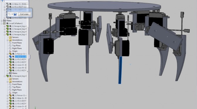
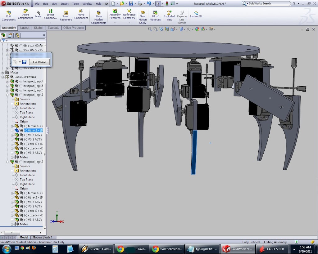
Great success! I learned CAD. Or rather Amy worked through the point I kept getting stuck on (a particular series of mates for the hexapod leg assembly), and then it was fairly easy sailing from there. Yay 🙂

not sure why it has 5 legs, might’ve hidden one when I screenshot’d

In other news, I didn’t make much headway on the pololu issue where something about my setup using Arduino + Pololu Mini Maestro is off (Dane showed me how to check with the multimeter to verify that the voltage was dropping to zero, aka symptoms of current limiting). I even took twenty minutes to wire everything to the original Arduino Nano (+ 2.007 carrier board) state, and verified that it did sound much… happier (yay the sound of 18 bloodthirsty happy servos =]). But I did read up more on serial and code, which was fun and hurt my head.

new robot brainz: Pololu Mini Maestro + Arduino

[Update, Jun 24 2010]: well now it actually works. see post: http://www.orangenarwhals.com/?p=197

My hardware:
Pololu Mini Maestro (24 ch serial RC controller)
Arduino Nano
1 servo
Some male header pins
A battery
A 2.007 Nano Carrier Board, which gives me easy access to the Arduino pins and a 5V supply
An 8V battery pack
Ubuntu 10.10 on my hp 2140 mini netbook

Steps:
Apply Powerz to Pololu and servos

TX/RX if needed
http://www.pololu.com/docs/0J40/7.c
specifically
http://www.arduino.cc/en/Reference/Board
http:// www.pololu.com/docs/0J40/1.b 

Apply codez
http://forum.pololu.com/viewtopic.php?f=16&t=3944

(put servo on pololu ch 0)

Hexaringapod rotate code

MEETERS  (MITERS end of term showcase) today! ’twas awesome, lots of people came (both MIT students and people from the area and people from artist’s asylum).

Anyway, I fixed the servo horn that a kid broke @ Cambridge Mini Maker Faire (10 minutes), then I scratched my head a lot over rotating my hexapod. In the end, trial and error code and fellow MITERians ftw.

Still KISS code that I’m embarrassed to publish, but I know I’ll find this useful in the future.
I rewrote the coxa in terms of rotating CW or CCW around the body, instead of backward and forward. Backward and forward were useful for the rectangular body, making it clear that moving coxa in the +J direction, “forward”, meant moving CW for servos on the left “half” of the body and CCW for servos on the right half. But now that I have a circular body, it just confused me (I couldn’t figure out how rotating was different walking forward, hah).

I don’t think I can get it to strife left / right with my current setup, where I’m pairing servos with Y splitter cables to get down to 12 channels, the max that the Arduino servo library supports.

(As it turns out, it is entirely possible to get more PWM outputs. David Lawrence, after I spammed everyone on MITERS asking for guidance, informed me that

http://www.arcfn.com/2009/07/secrets-of-arduino-pwm.html 

Essentially, because the PWM waveform is output at 1000 Hz, it’s necessary to use the hardware timers, which only connect to a subset of the output pins.  However, servos are quite happy to be driven by a 50 Hz PWM, in which case you can use one timer to control a whole bunch more of the GPIO pins.  The higher frequency is only really necessary for interfacing with analog hardware.  

 )

Vid:

Code:

 #include <Servo.h>

#define TIBIA 45
#define DELAY 300

#define COXA_CCW 70
#define COXA_CW 105

/*
~front~
A D
B E
C F
~back~
*/

#define AC_UP 92
#define AC_DOWN 125

int UP = AC_UP;
int DOWN = AC_DOWN;

Servo E_coxa;
Servo E_femur;
Servo E_tibia;

Servo B_coxa;
Servo B_femur;
Servo B_tibia;

Servo AC_coxa;
Servo AC_femur;
Servo AC_tibia;

Servo DF_coxa;
Servo DF_femur;
Servo DF_tibia;

void setup()
{
digitalWrite(2, OUTPUT);
digitalWrite(3, OUTPUT);
digitalWrite(4, OUTPUT);
digitalWrite(5, OUTPUT);
digitalWrite(6, OUTPUT);
digitalWrite(7, OUTPUT);
digitalWrite(8, OUTPUT);
digitalWrite(9, OUTPUT);
digitalWrite(10, OUTPUT);
digitalWrite(11, OUTPUT);
digitalWrite(12, OUTPUT);
digitalWrite(13, OUTPUT);

pinMode(1, OUTPUT);
pinMode(2, OUTPUT);
pinMode(3, OUTPUT);
pinMode(4, OUTPUT);
pinMode(5, OUTPUT);
pinMode(6, OUTPUT);
pinMode(7, OUTPUT);
pinMode(8, OUTPUT);
pinMode(9, OUTPUT);
pinMode(10, OUTPUT);
pinMode(11, OUTPUT);
pinMode(12, OUTPUT);
pinMode(13, OUTPUT);

E_coxa.attach(2);
E_femur.attach(3);
E_tibia.attach(4);

B_coxa.attach(5);
B_femur.attach(6);
B_tibia.attach(7);

AC_coxa.attach(11);
AC_femur.attach(12);
AC_tibia.attach(13);

DF_coxa.attach(8);
DF_femur.attach(9);
DF_tibia.attach(10);

}

void loop()
{
for (int i=0; i<=2; i++){
walkfwd();
}
for (int j=0; j<=2; j++){
walkbwd();
}
for (int k=0; k<=2; k++){
turnleft();
}
for (int l=0; l<=2; l++){
turnright();
}


}
void walkbwd() {
tibia();
b1();
b2();
b3();
b4();
}
void walkfwd() {
tibia();
tri1();
tri2();
tri3();
tri4();
}

void turnleft() {
tibia();
l1();
l2();
l3();
l4();
}

void turnright() {
tibia();
r1();
r2();
r3();
r4();
}
void tibia() {
AC_tibia.write(TIBIA);
B_tibia.write(TIBIA);
DF_tibia.write(TIBIA);
E_tibia.write(TIBIA);
}

void tri1() {
AC_coxa.write(COXA_CW);
E_coxa.write(COXA_CCW);

DF_coxa.write(COXA_CW);
B_coxa.write(COXA_CCW);

delay(DELAY);
};
void tri2() {
AC_femur.write(AC_DOWN);
E_femur.write(DOWN);

DF_femur.write(UP);
B_femur.write(UP);

delay(DELAY);
};

void tri3() {
AC_coxa.write(COXA_CCW);
E_coxa.write(COXA_CW);

DF_coxa.write(COXA_CCW);
B_coxa.write(COXA_CW);

delay(DELAY);
};
void tri4() {
AC_femur.write(AC_UP);
E_femur.write(UP);

DF_femur.write(DOWN);
B_femur.write(DOWN);

delay(DELAY);
};


void b1() {
AC_coxa.write(COXA_CCW);
E_coxa.write(COXA_CW);

DF_coxa.write(COXA_CCW);
B_coxa.write(COXA_CW);

delay(DELAY);
};
void b2() {
AC_femur.write(AC_DOWN);
E_femur.write(DOWN);

DF_femur.write(UP);
B_femur.write(UP);

delay(DELAY);
};

void b3() {
AC_coxa.write(COXA_CW);
E_coxa.write(COXA_CCW);

DF_coxa.write(COXA_CW);
B_coxa.write(COXA_CCW);

delay(DELAY);
};
void b4() {
AC_femur.write(AC_UP);
E_femur.write(UP);

DF_femur.write(DOWN);
B_femur.write(DOWN);

delay(DELAY);
};


void l1() {
AC_coxa.write(COXA_CCW);
E_coxa.write(COXA_CCW);

DF_coxa.write(COXA_CW);
B_coxa.write(COXA_CW);

delay(DELAY);
};
void l2() {
AC_femur.write(DOWN);
E_femur.write(DOWN);

DF_femur.write(UP);
B_femur.write(UP);

delay(DELAY);
};

void l3() {
AC_coxa.write(COXA_CW);
E_coxa.write(COXA_CW);

DF_coxa.write(COXA_CCW);
B_coxa.write(COXA_CCW);

delay(DELAY);
};
void l4() {
AC_femur.write(UP);
E_femur.write(UP);

DF_femur.write(DOWN);
B_femur.write(DOWN);

delay(DELAY);
};


void r1() {
AC_coxa.write(COXA_CW);
E_coxa.write(COXA_CW);

DF_coxa.write(COXA_CCW);
B_coxa.write(COXA_CCW);

delay(DELAY);
};
void r2() {
AC_femur.write(DOWN);
E_femur.write(DOWN);

DF_femur.write(UP);
B_femur.write(UP);

delay(DELAY);
};

void r3() {
AC_coxa.write(COXA_CCW);
E_coxa.write(COXA_CCW);

DF_coxa.write(COXA_CW);
B_coxa.write(COXA_CW);

delay(DELAY);
};
void r4() {
AC_femur.write(UP);
E_femur.write(UP);

DF_femur.write(DOWN);
B_femur.write(DOWN);

delay(DELAY);
};

and as always, pics:
https://picasaweb.google.com/nancy.ouyang/2007HexapodSpring2011