I got a gripper from some very nice SteadyWin folks at the boston robotics expo (part of boston robotics week / boston tech week) and finally got it working last week!!
After chatting with the steadywin folks on wechat, I got a link to their wiki.
The relevant pages are
- for the memory table which specifies where to write/read https://coremotion.feishu.cn/wiki/ZkEJwOcHaiAEk8kC18Jc9ej9noc?sheet=ar6hDm
- as well as some demo python code https://coremotion.feishu.cn/wiki/CaLbwkWsdib0ctko2kFcCO9Fnlf
- and the CAN protocol spec
https://coremotion.feishu.cn/wiki/OzeLwRUasiIb2FkYaezczQzJnyf (I found this document more helpful after I had a handle on what was going on [4])
How motor talk = registers
The way these quasi direct-drive (QDD — has small planetary gearbox, not direct drive) brushless DC (BLDC) motors with integrated controllers (driver is built into the housing) work: you write to a register to control the motor and read from the register to get statuses.
On to the practical part:
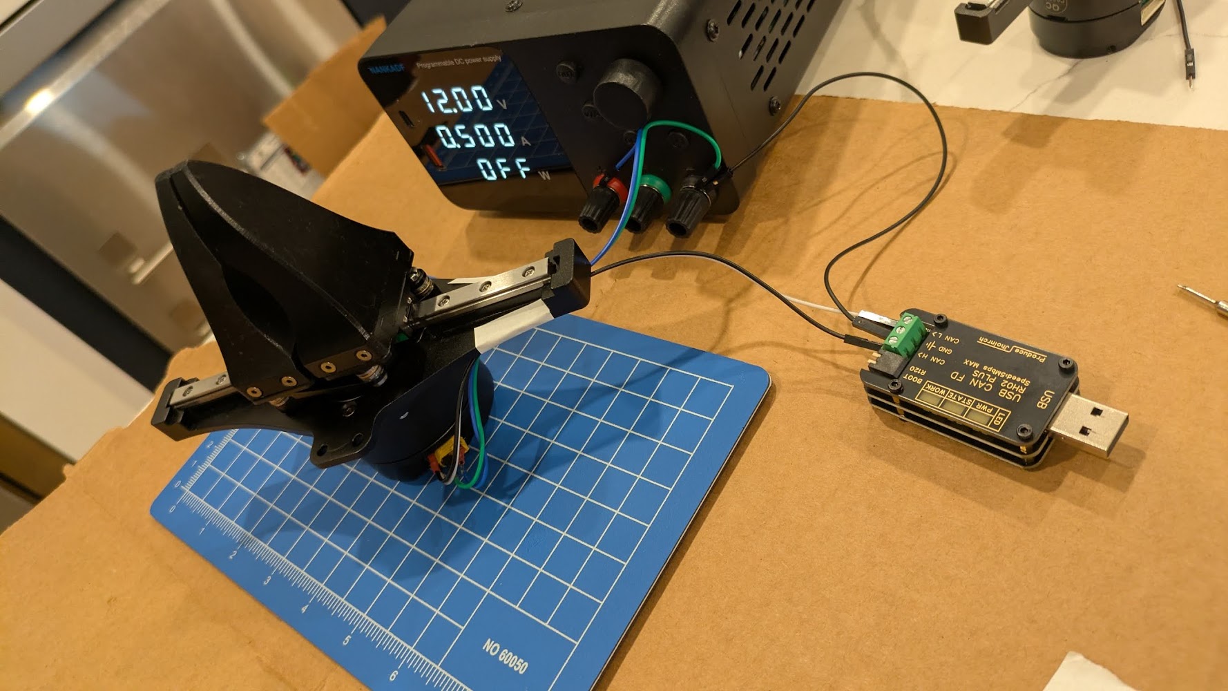
Hardware setup
- Get a Steadywin gripper (in the $150-200 range after shipping and fees)
- Buy an XT30(2+2) cable ($15). This looks like an XT30 but has two small data pins on the side. Amazon search makes this remarkably impossible to find. The term apparently is”3meters CAN Cable 2 in 1 Power Data Cable 3D Printer XT30(2+2)”
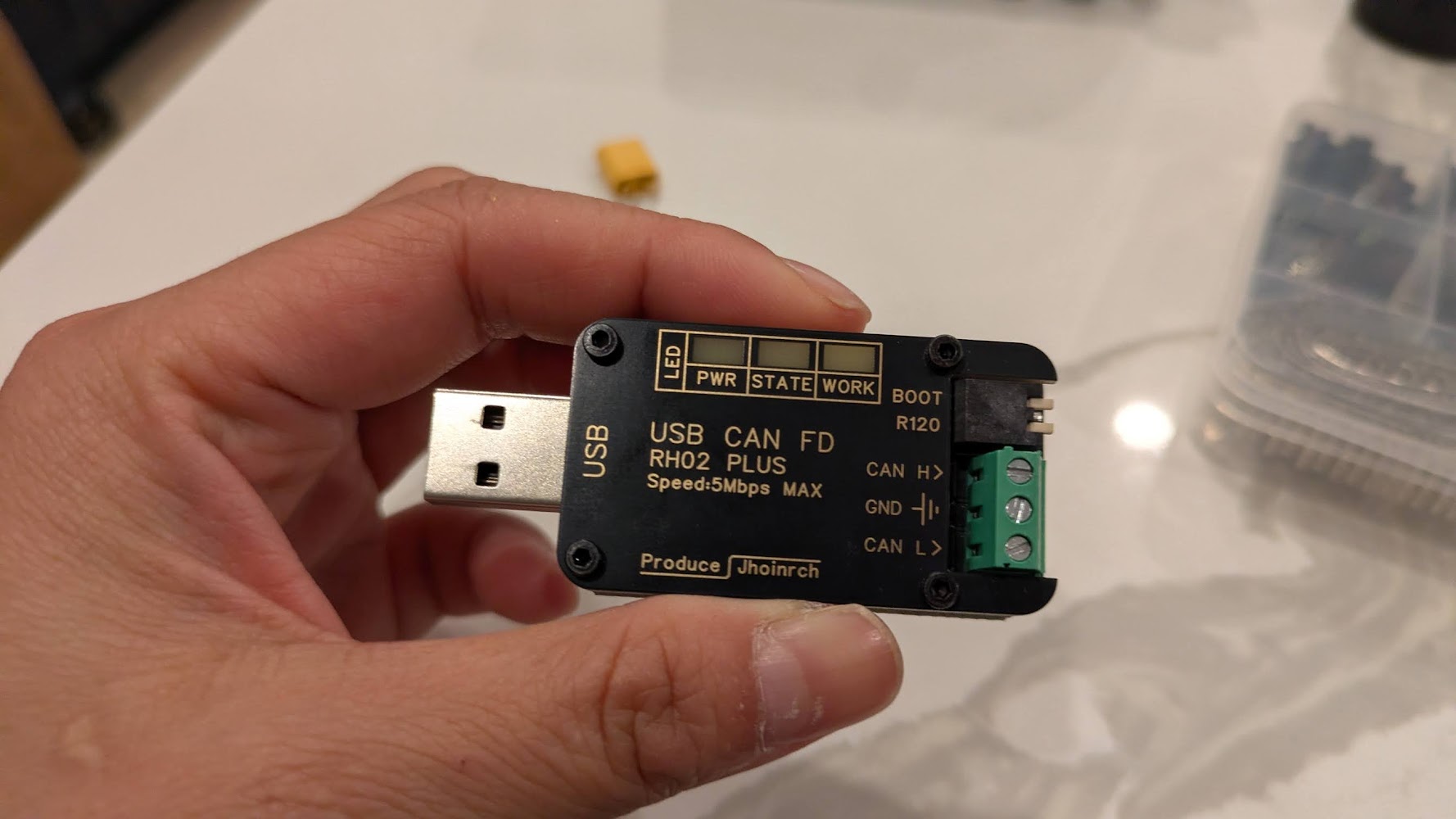
https://www.amazon.com/HOCENWAY-CAN-Compatible-Micromotor-Connection/dp/B0DBY3W51J/ - Buy a USB CAN Adapter ($15-20)
http://amazon.com/gp/product/B0F9F9J3WN/ - Buy a bench power supply while you’re at it, they’re so light nowadays ?! The motor wants ~24V.
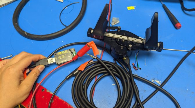
The XT30(2+2) consists of the fat motor power wires and two small signal wires. [6]
Plug in the cable, then connect to 1) the power supply and 2) the USBCAN device.
After wiring up the gripper, make sure to also:
** Connect USB CAN to laptop. **
** Turn on power to motor **
Don’t forget the above steps 🙂
Software setup
I got this working in Linux with the Steadywin motors.
In a nutshell:
$ uv venv
$ uv pip install python-can

$ sudo slcand -o -c -s8 /dev/ttyACM2  # [1]
$ sudo ip link set can0 up txqueuelen 1000 # [2]

# In a new terminal:
$ candump can0 # Listen to all the CAN messages back and forth
CANSEND? CANDO!
Sending CAN commands by hand
The overall flow
Check the motor is talks back and where it thinks it is using #280204 (ask for current position, should get a response from the motor), #21000103FFFFFF (set to position control), #34000101FFFFFF (set position to zero so we don’t get unexpected big movement — this needs to happen while torque is off, and we should get 01 in response, not 00), #00020101FFFFFF (torque on), #14020400040000 (command a position), #00020100FFFFFF (torque off).
The commands I used
cansend can0 001#01                  # ping — confirm it answers
cansend can0 001#02                  # status
cansend can0 001#280204              # read position
cansend can0 001#21000103FFFFFF      # mode = position (0x03, FFFFFF is for padding)
cansend can0 001#280204              # read position
cansend can0 001#34000101FFFFFF      # [3] set position to zero -- should get 01 as response, not 00 !
cansend can0 001#280204              # read position
cansend can0 001#00020101FFFFFF      # torque on (0x01)
cansend can0 001#14020400040000      # goal +1024
cansend can0 001#280204              # read position
cansend can0 001#00020100FFFFFF      # torque off (0x00)
cansend can0 001#02                  # check motor still alive. I use this because it's easy to remember
SUCCESS!!!!!!!111111!!!
The first high was when the motor actually talked back, the second was when it finally moved !!!!!!!!!!!!111111111!!!!!!!!!!!!!1
Parenthetical Notes
[1] Use sudo dmesg | tail to find the port, you’ll see something like […] ttyACM2: USB ACM device. (See later section on udev for how to fix it so the address doesn’t change each time you plugin the device).
[2] The TX Queue length increases the buffer so that while the motor is still processing a command, incoming commands may not get dropped. AFAIK.
[3] Reading candump. The successful reply looks like the following, where (can0 = the interface, 001 = motor CAN id, [1] for length of message, 01 for message — aka success)
can0 001 [1] 01
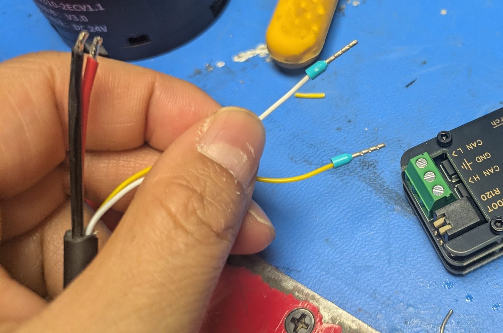
[6] Iif you’re fancy you can terminate the XT30(2+2) data wire in wire ferrules with a crimper, then they fit nicely into the usb can headers)
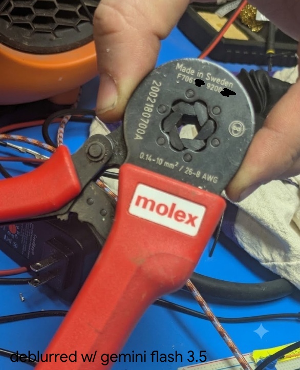
(the bad focus annoyed me so I asked gemini to deblur, but I censored the hallucinated serial number)
If you’re excited to read more about ferrule crimpers, see this post.
[4] The confusing CAN documnt: e.g. ID(7) means device id register is at address 7 (and here it defaults to 001), not the ID is 7. Also — the English version of the CAN protocol document says “ByteDance” everywhere, when it just means “byte”. (ByteDance wrote Tiktok, in case the name sounds familiar). So it’s quite confusing to read… T__T
Learning to Read
anyway so what do all these mysterious numbers mean? let’s dive in
Deciphering cansend can0 001#280204 (Read command)
cansend can0 001#280204
Byte order
As per the docs, “all multi-byte register content transmissions use little-endian byte order , i.e., the low-order byte first and the high-order byte last”.
MIT Protocol (not MIT controller)
The MIT protocol is a spec for how bytes are laid out on the CAN bus, (and is separate from MIT mode/MIT controller, which is the torque impedance type of controls). The protocol runs over CAN bus and uses 11-bit frames and the message type is determined by length, i.e. 1 byte for ping and status, 3 for reads, 7 for writes, and 8 for commands.
Current Location
So we know that we want to send a 3 byte message.
We then come to the SIAR motor table.
| Memory Address | Function | Bytes | ||
| DEC | HEX | MODBUS ADDR | ||
| 552 | 228 | 40277 | Current Location | 4 |
We also see from the CAN Communication Control Protocol v2, under “Read Register”.
| DATA0 | DATA1 | DATA2 |
| Address (L) | Address (H) | Len |
Thus taking
001#280204
We can parse that into the bytes, 28-02-04, then flip since we’re in little endian, so 0x0228, and then the final is 4.
Type of returned position
So we expect to read 4 bytes — in other words the a 32bit value for the position. In the provided example python file we see:
PRESENT_POSITION = 0x228
pos_raw_bytes = motor_comm.read_register(motor_id, PRESENT_POSITION, 4)
if pos_raw_bytes and len(pos_raw_bytes) == 4:
    pos_raw = struct.unpack('<i', pos_raw_bytes)[0]
I was new to the whole struct situation. Referring to the python docs. https://docs.python.org/3/library/struct.html#format-strings
https://docs.python.org/3/library/struct.html#format-characters
so the < specifies little endian, then the lowercase i specifies a signed int.
Parsing the position
Again from the demo python code,
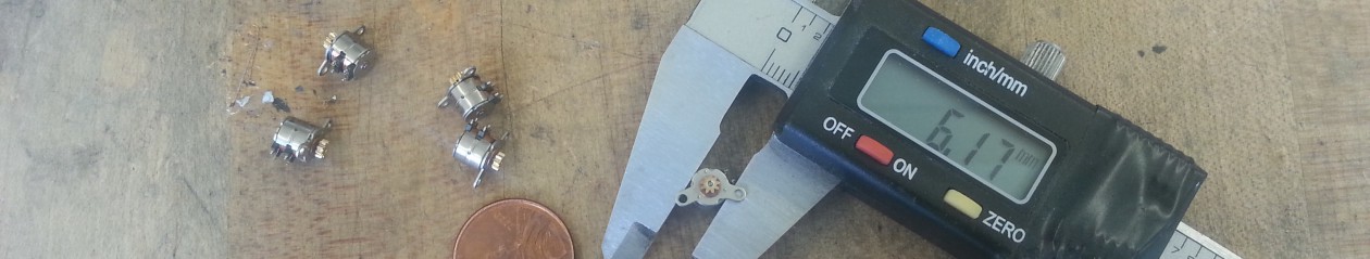
RAD_TO_SIGNAL = 2607.5946This is equivalent to
(2^14)/(2*pi) = 16384 pulses / 2π radians ~= 2607That is, an encoder that has 14-bit resolution across one revolution (2*pi). So we have 16384 pulses per revolution, and a single pulse is then about 0.02 degrees of revolution. (To verify: this is probably the position of the motor stator not of the output shaft (since there’s a planetary gearbox I think), then there’s a further translation to the position of the gripper jaws).
Deciphering cansend 001#00020101FFFFFF (Write command)
We can read from the table under the “hex” column
| Hex 200 |
Function Torque Switch |
Bytes 1 |
Scope 0 ~ 1 |
We know that the write command needs to be 7 bytes. It should go to 0x200 memory address. And the length is 1, and the value is 0 or 1.
So we have:
00 02 01 01 [Pad out to 7 bytes]
I had my handy word salad machine write out this diagram out 🙂
001#00020101FFFFFF
    └─┬┘ │└──┬───┘
      │  │   └── value 01 + FF padding
      │  └─ length 1
      └─ register addr 0x0200
Debugging
I didn’t mean this to come across so tutorial-like. The story of the post was meant to be a bit more … here’s the bugs I ran into. A short list.
Bug: I could see from candump that I was sending out pings, but not getting responses
Debug: I hadn’t turned on power to the motor, only plugged in the USB CAM heh. classic.
Bug: The motor would accept pings, torque on, move successfully, then I’d send it a torque off command, and then when I tried to send pings or torque ons, it stopped responding.
Debug: Turned out, I usually turned the gripper off to reposition the motor (since I only cannot go to a + position, not a – position, and I hadn’t rezerod), and when I moved the gripper too fast by hand, presumably the back current going into the motor driver would cause a fault state in the CAN.
This was particularly annoying since I’d have to unplug and replug in the CAN and type in like 5 commands to get back to the same state, since I haven’t set up persistent naming of the device it would increment from ttyACM9 to ttyACM10 etc.
Bug: I knew zeroing command was correct since I’d used it before, but then the motor would not zero and show sudden movement.
Debug: If I looked more closely the motor was sending “00” in response, saying the write had not happened. If I read the docs this is because the register is in EEPROM (persists across reboot) and writes are only during torque off state).
Notes
Todo: Persistent Device Name
I should sleep, so please refer to:
Edit the file with the following:
# vi /etc/udev/rules.d/70-can-persistent.rules [5]
SUBSYSTEM=="net", ACTION=="add", KERNEL=="can*", ATTRS{serial}=="YOUR_SERIAL_HERE", NAME="can0

# Then reload
sudo udevadm control --reload-rules
The values can come from running dmesg | tail —
[ 2029.193842] usb 2-2: new full-speed USB device number 13 using xhci_hcd
[ 2029.322042] usb 2-2: New USB device found, idVendor=16d0, idProduct=117e, bcdDevice= 2.00
[ 2029.322060] usb 2-2: New USB device strings: Mfr=1, Product=2, SerialNumber=3
[ 2029.322067] usb 2-2: Product: CANable2 b158aa7 github.com/normaldotcom/canable2.git
[ 2029.322072] usb 2-2: Manufacturer: Openlight Labs
[ 2029.322077] usb 2-2: SerialNumber: 207635634E45
[ 2029.326088] cdc_acm 2-2:1.0: ttyACM2: USB ACM device
Notes
[5] (70 denotes the rough order/priority for udev, the (l)inux device manager to process after the device is plugged in)
Reference: SocketCAN
https://wiki.st.com/stm32mpu/wiki/How_to_set_up_a_SocketCAN_interface
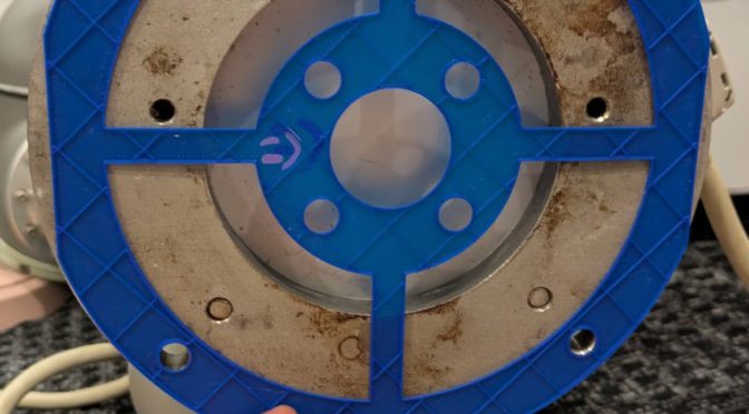
Reference: Gripper hardware design
Of note, maybe I want more grippers, there is actually an open-source version of a similar gripper mechanism, made to fit around a DaMiao branded gripper.
https://wiki.seeedstudio.com/dm_gripper/
next steps
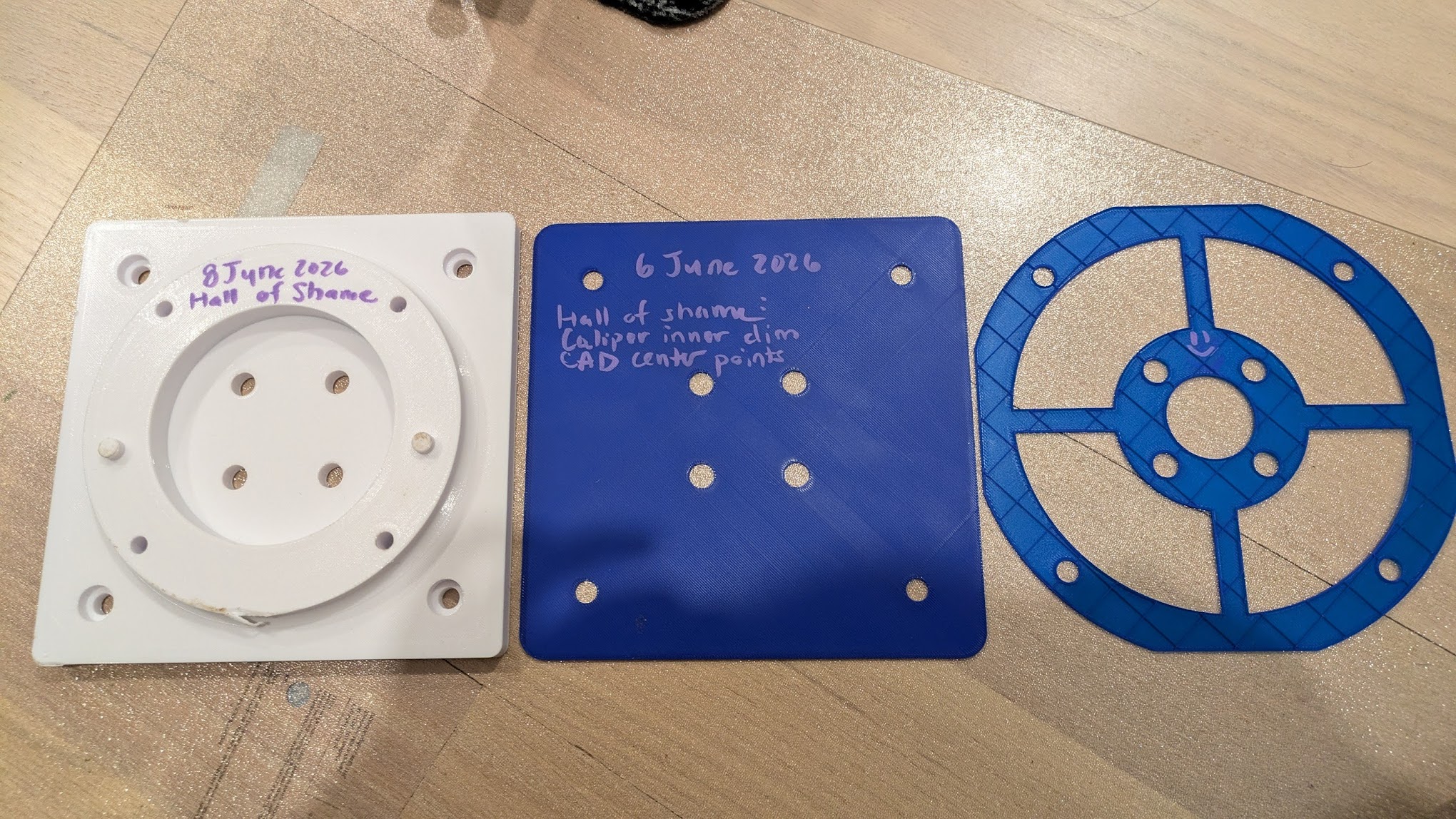
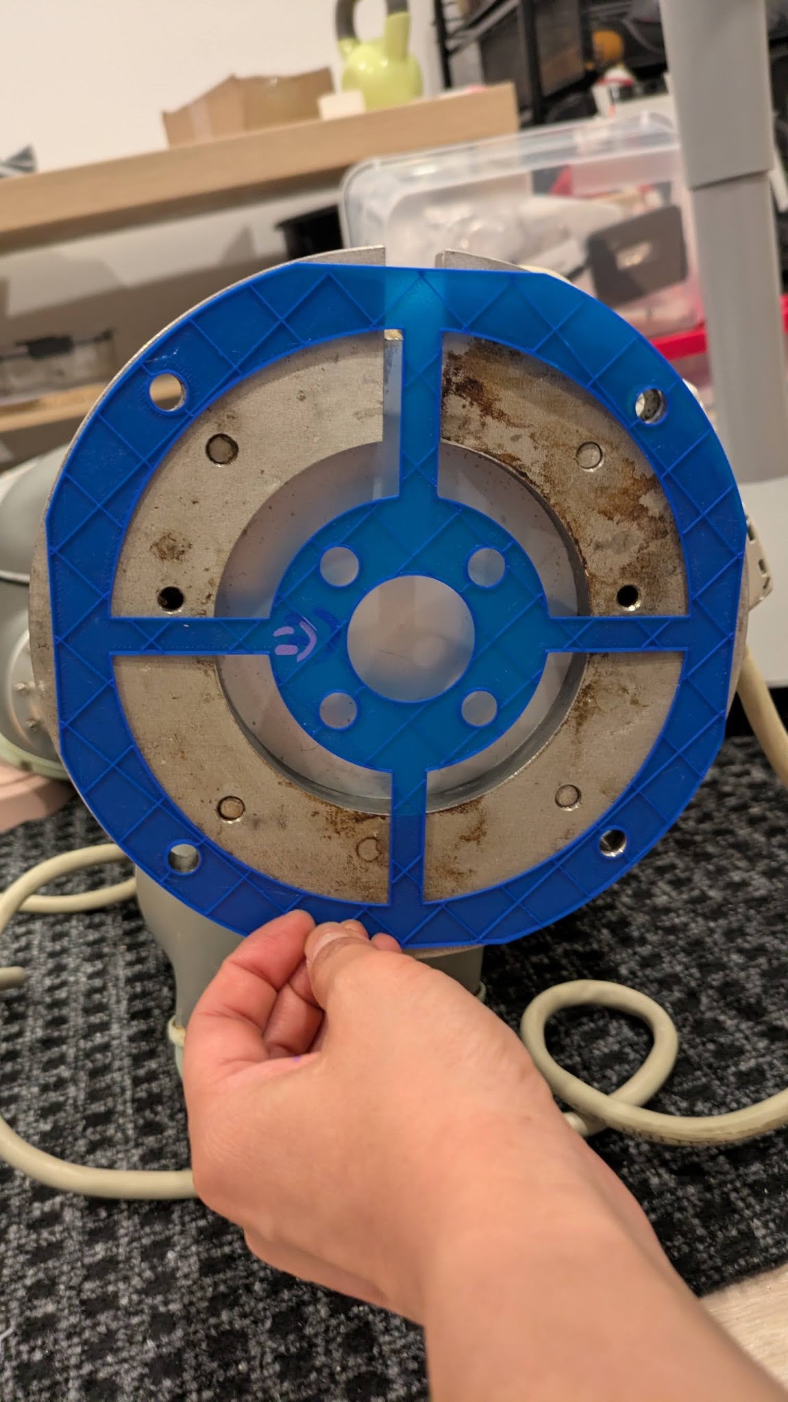
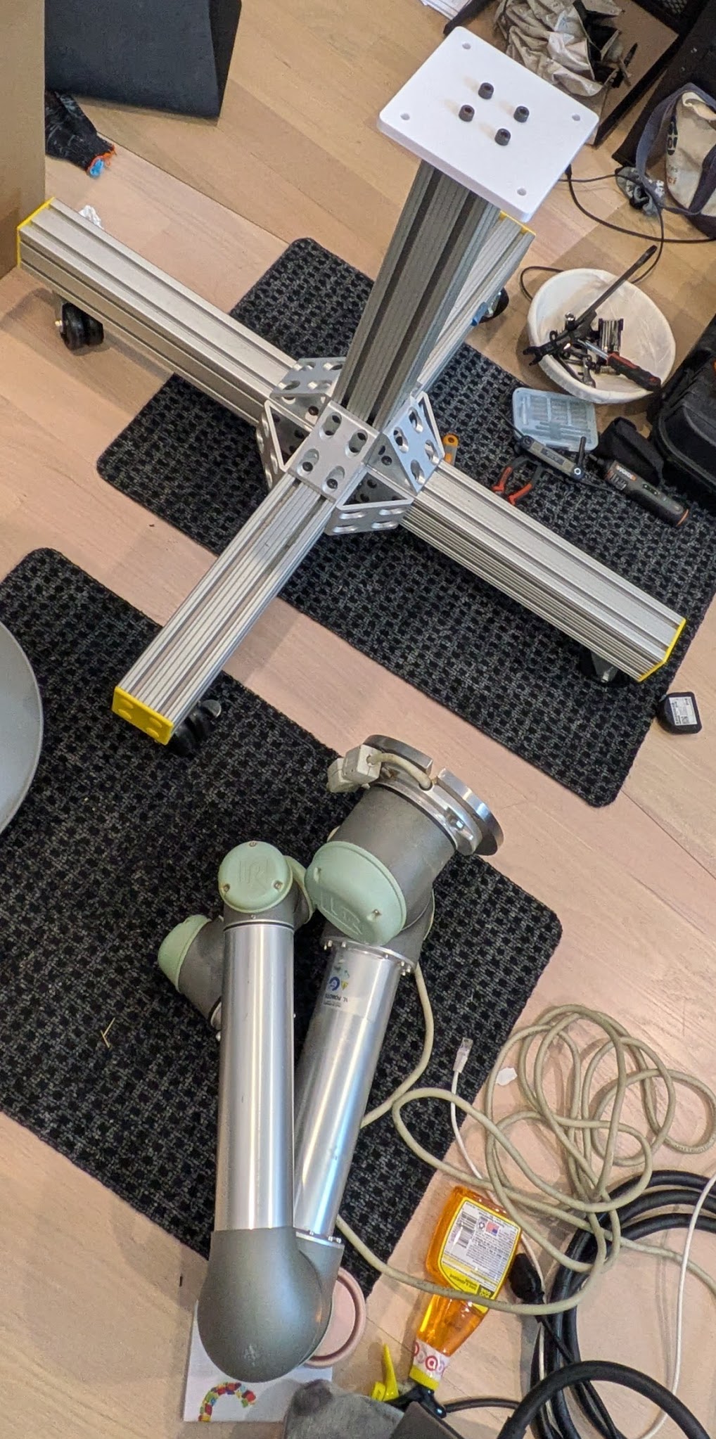
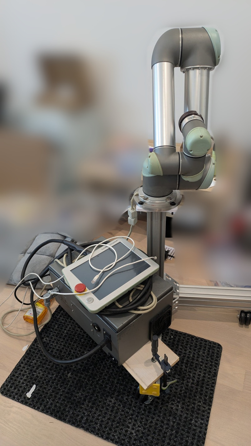
zzz next steps: actually mounting this the UR5, which requires some 3d printing and some cabling.
the end, but i just remembered the other update:
zzzz.
i was supposed to make a cool robot demo with software skills, but i’m still stuck in hardware land right now. but i’m having a lot of fun figuring things out. i find it easy to vortex people the people around me into enthusiasm about real life robots since well, they’re a bunch of roboticists too — don’t quite have the same with software / deep learning yet. but yea!
tld;r robotsssssssszzzzzzzz.
fin.