
starting work again.

nyancake
Uhh I’ve been doing a lot of blogging and neglecting my other work, so here is minimalist style ftw.
 |
| nyancake? nyangummi? |
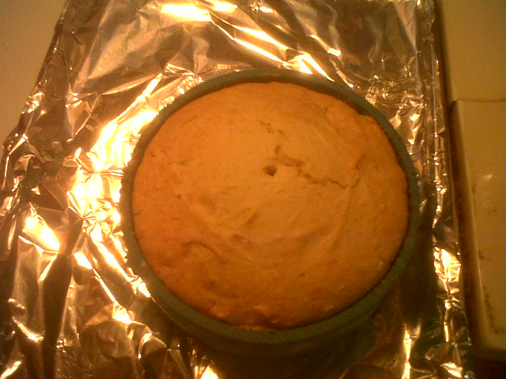
My hall’s thanksgiving (putzgiving, alums come back for this) was two Saturdays ago. I tested out the nyancat cake mold:
 |
| for ease of “parameter optimization” runs, I used even-simpler-cake-recipe: cake mix and sprite as the only ingredients (apparently a dieting trick. comes out fine, although for molds probably want to let bubbles settle for a bit after pouring and before intensive mixing). |
 |
| apply release agent, aka cooking spray / pam — otherwise doesn’t come out well. also, sprite+cakemix mixture should not be too gloopy. add flour if accidentally pour too much sprite. |

 |
| many fail results. Here, did not let bake long enough. (much longer than box says — I baked a bit lower temp based on silicone mold research, ~325deg C, and for say 1 or 2 hours) |
 |
| demolded too quickly, also did not cover in saran wrap to retain moisture afterward |
 |
| nyancake party~! nyan nyan nyan |
|
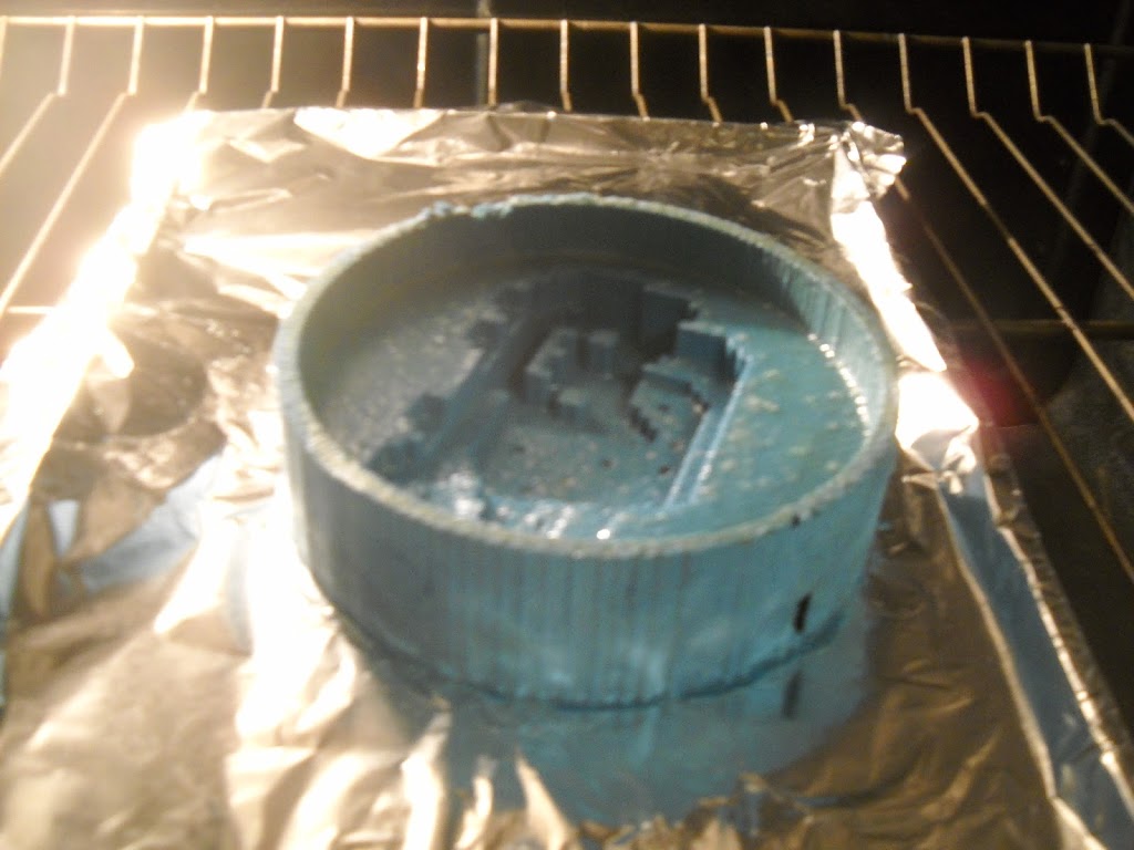
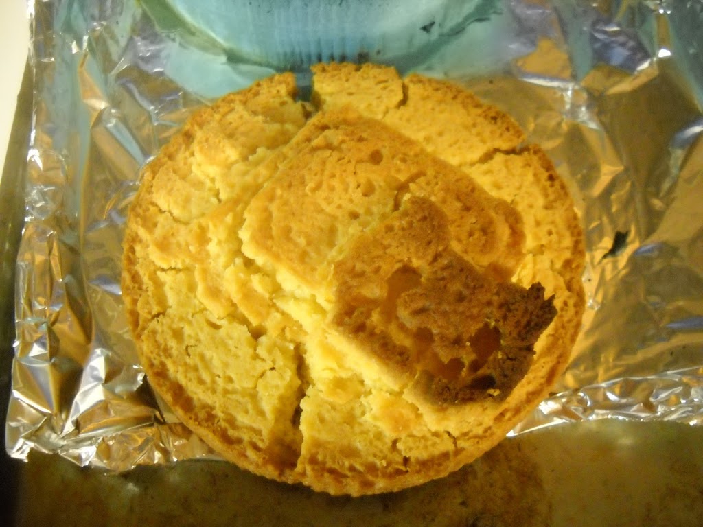
| probably the best of all my nyancakes. you can see that the minimum mold feature size — the sprinkles — were too small for the resolution of the cake mix and actually resulted in holes. |
 |
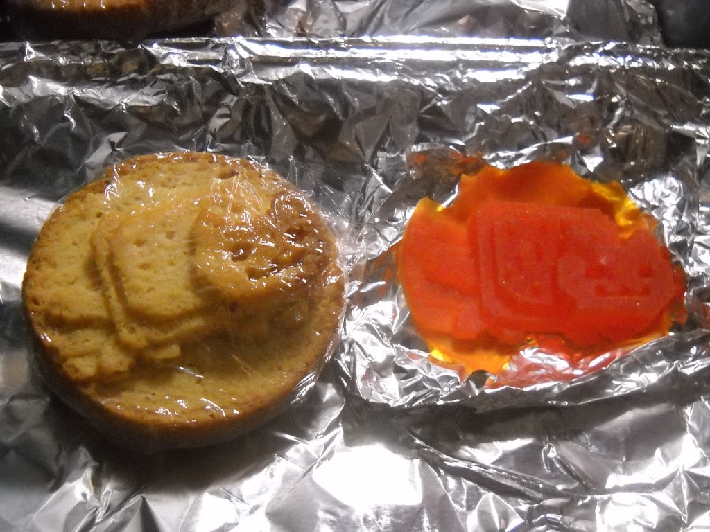
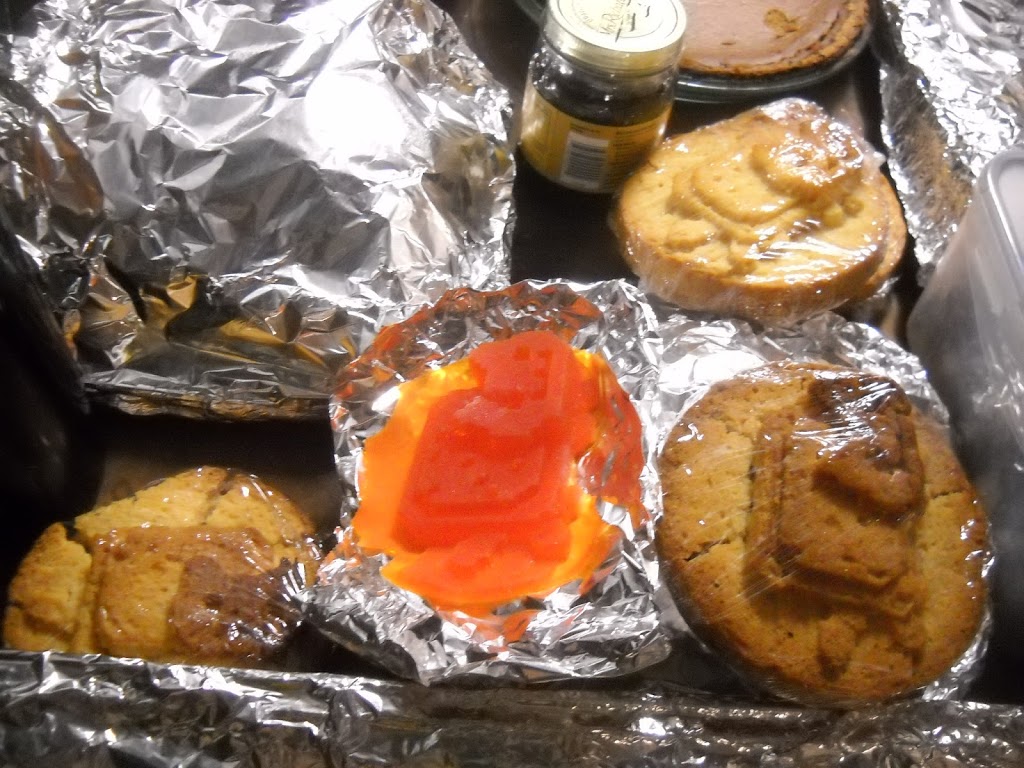
| speed cooling jello in freezer. recipe used: the lego gummies from instructables |
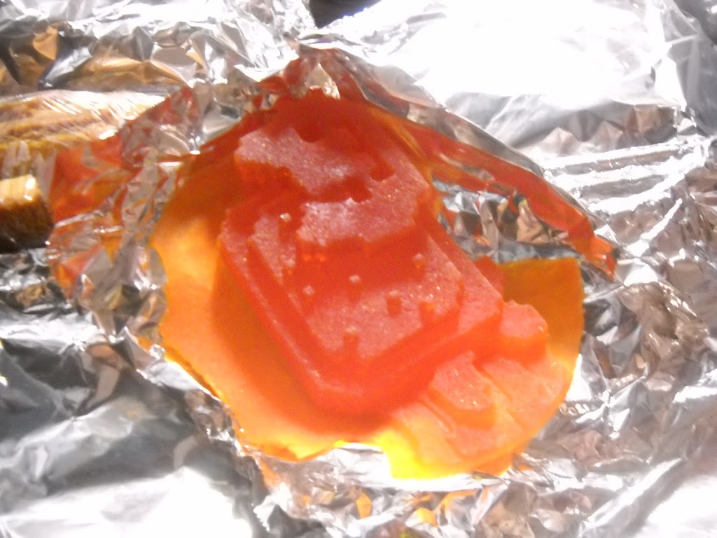 |
| nyanjello = almost perfect mold replica. you can see the sprinkles are supposed to stand out, as opposed to how the nyancakes turned out. however, more limited / difficult coloring opportunities with jello than with cake (which you can just apply frosting / food coloring to) |
Class-based makefile includes:
avr-objcopy -j .text -O ihex ./v0.1.45.out ./v0.1.45.c.hex
man avr-objcopy
-j sectionname
–only-section=sectionname
Copy only the named section from the input file to the output file.
This option may be given more than once. Note that using this
option inappropriately may make the output file unusable. >__> <__<
So the class makefiles should be fixed to include “-j .data”The internet says
“The makefile above DOES NOT create a proper HEX image and is a bad example. When creating an image, not only does the text section (which holds the code) need to be included but the data section (which holds any initialized data) also needs to be included.
The remedy for this is correct .hex rule to to copy the data setion as well
Example:
$(OBJCOPY) -j .text -j .data -O ihex $(PROJECT).out $(PROJECT).hex
” http://www.micahcarrick.com/avr-tutorial-digital-output.html
bmayton: that actually explains a lot of odd bugs that I’ve been seeing with peopleusing constant arrays, since the array data is never getting copied into the
program
So the actual model of what was causing my bug was, I believe, without calling another function the compiler goes ahead and uses the array to insert the correct commands into the compiled code. But when I used a subfunction, the compiler loads the subfunction which the microcontroller calls, but the ucontroller does not have the array data to look up what to set DDRB and PORTB to.
Anyway, then I proceeded to hack together terrible!code and get PoV working. I used oloepede’s sample image ‘cos I’m all about the laziest and quickest tests and ‘cos olopede is awesome.
 |
| eheh derp ripped off ISP traces / headers |
 |
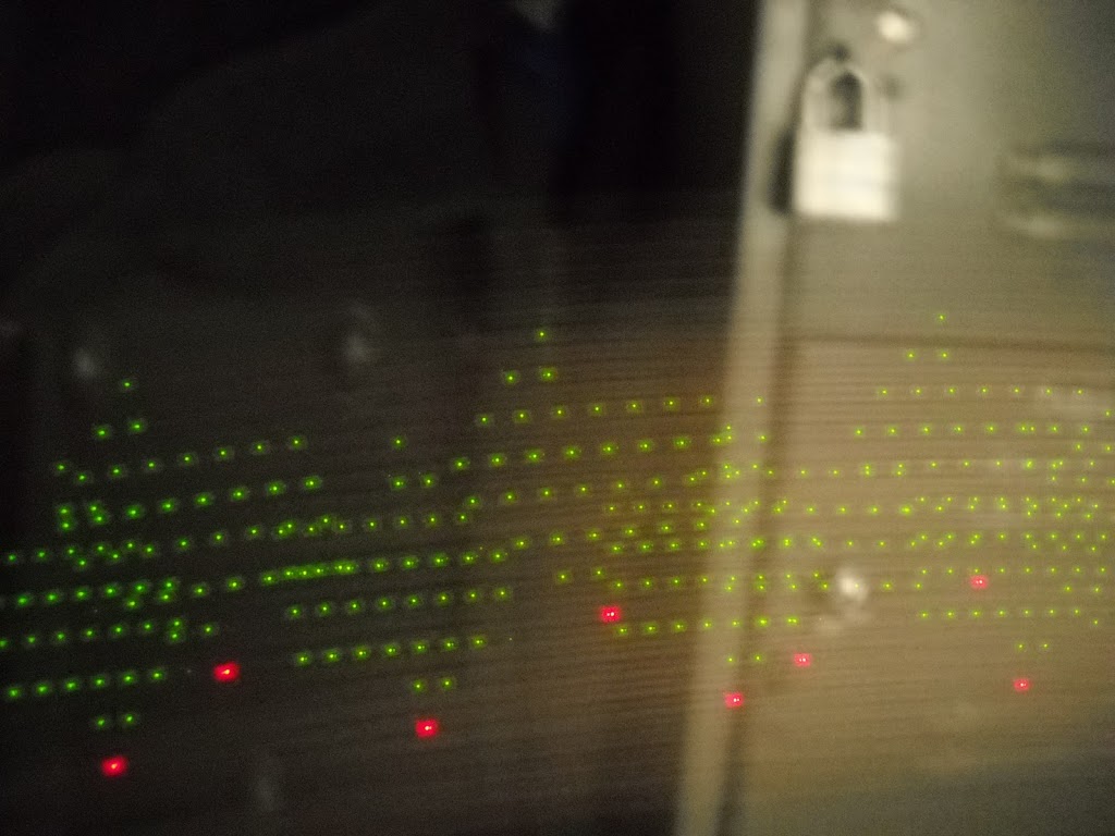
| works fine waving it by hand (without camera extended exposure time, hard to see entire “olopede” message — can see maybe three letters at a time. dead reckoning PoV timing — no sensors.) |
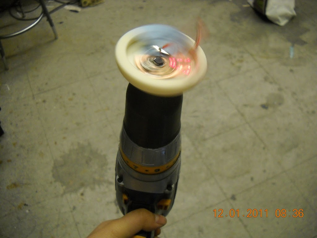
Doesn’t do so hot on the drill. Mess with timing? Although I spun it slow and fast (and in-use yoyo spins quite fast). May require sensors (fan pov as seen on dealextreme — product designer has better idea of speed of motor while yoyo has more variable speed. maybe they used hall effect sensors, ‘cos it was resilient to me slowing down the blades.) to get stable image.
See video:
https://picasaweb.google.com/113942194695013581888/PoVYoyoPersistenceOfVision#5681157457783660930
Vending machine
Right, essentially two weeks until final projects due. Aka time to start cramming on vending machine.
What do I have on hand? Arduino uno, extra servos leftover from when I bought out all the old 2.007 servos., zipties, handheld drill, a corkscrew. Found some rectangular metal thing to act as guiderails lying around MITERS scrap pile. Also found a block of wood lying around the floor.
Mod a servo to be
continuous rotation servo
(essentially turn it into a cheap RC motor that comes with motor speed controller in a convenient package for mounting) —
aka remove mechanical stop on gear
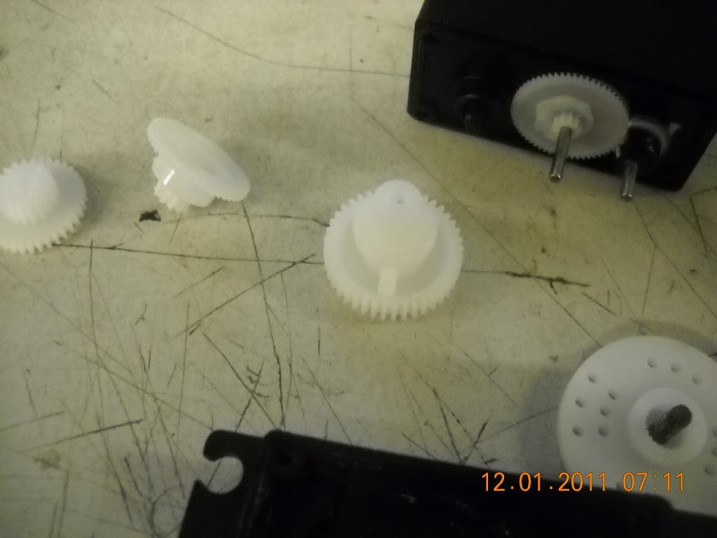 |
| apply flush cutters to stop on gear |
and remove pot, which like all pots doesn’t turn infinitely — make sure to be gentle ‘cos pot is held in by internal screw, why it doesn’t just fall out normally
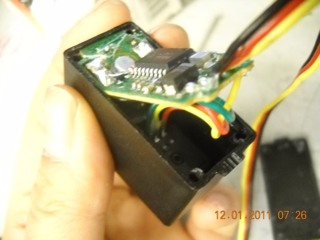 |
| see blurry screw at bottom. Also, I wasn’t gentle and cracked the PCB. Maybe it is inevitable for these servos (motor is soldered onto pcb so not much flexibility there) to get to pot screw. Surprisingly the servo still works… |
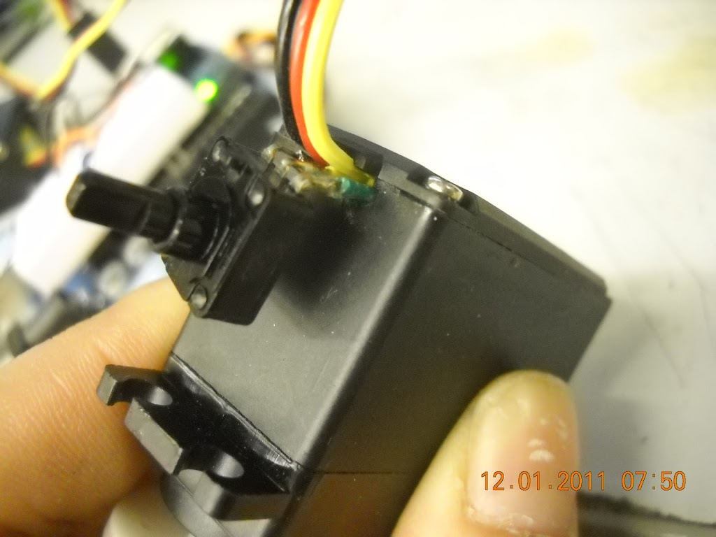 |
| stick pot on outside, chew a hole for it in the casing — i abused flush cutters |
see How to Hack a Servo by Daniela Faas http://stellar.mit.edu/S/course/2/sp11/2.007/courseMaterial/topics/topic12/other/Servo_Hack_large/Servo_Hack_large.pdf)
springs / coils
Attach to corkscrew (from real vending machine) I bought off of ebay to see what real mass manufactured ones are like so I can make fake ones DIY like http://www.instructables.com/id/Make-your-own-springs-in-seconds/

Drill out servo horns (1/8” bit fits zipties I found) and attach to corkscrew with zipties
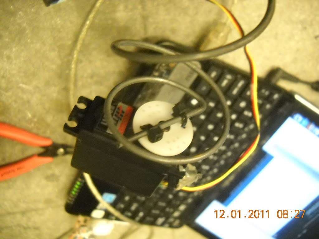
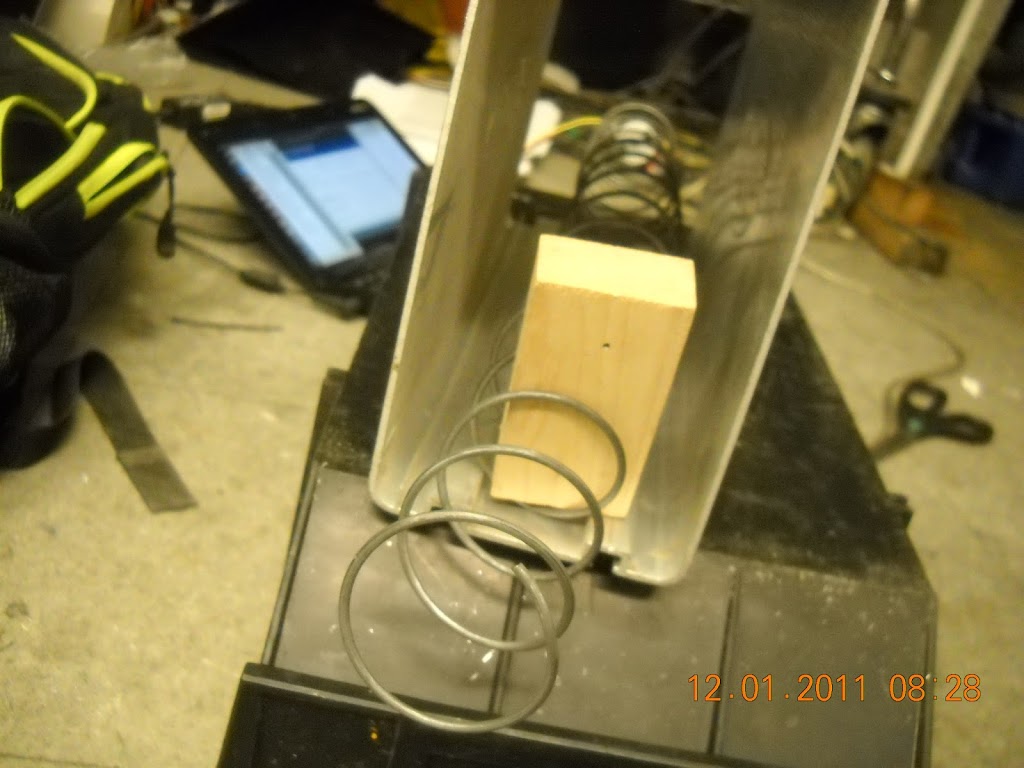 |
| it vends a block! haha. terrible setup is terrible. |
Video here:
https://picasaweb.google.com/113942194695013581888/VendingMachineOpenHardware#5681154916854562050
Yea, not a very interesting proof-of-concept (a “duh are you an idiot” one), but it was very satisfying to me.
Oh right, I tried to use hot glue to hold the pot in one place, since that affects how the servo reacts to servo.write() (pot adjusts when it goes fwd/reverse) — I just used
myServo.write(50) with a 0.5 sec delay
myServo.write(90) with a 3 sec delay
myServo.write(130) with a 0.5 sec delay
to calibrate the pot so that servo was completely still at 90. And then attempted to hot glue. a bit flaky– not good enough for long-term banging around but good enough for dirty proto.
 |
| yes, i stole arduino from hexarideablepod. arduino uno with a small breadboard on top and 3 male header pins to connect arduino (Vcc, Gnd, and SIG — arbitrarily pin 2 in my case) and servo. unplugged in this pic. |
Not clear from pics, but to test it I’m holding the servo still with my hand.
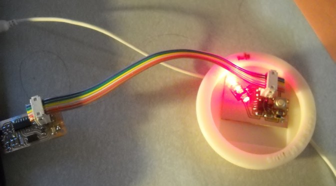
PoV yoyo update:
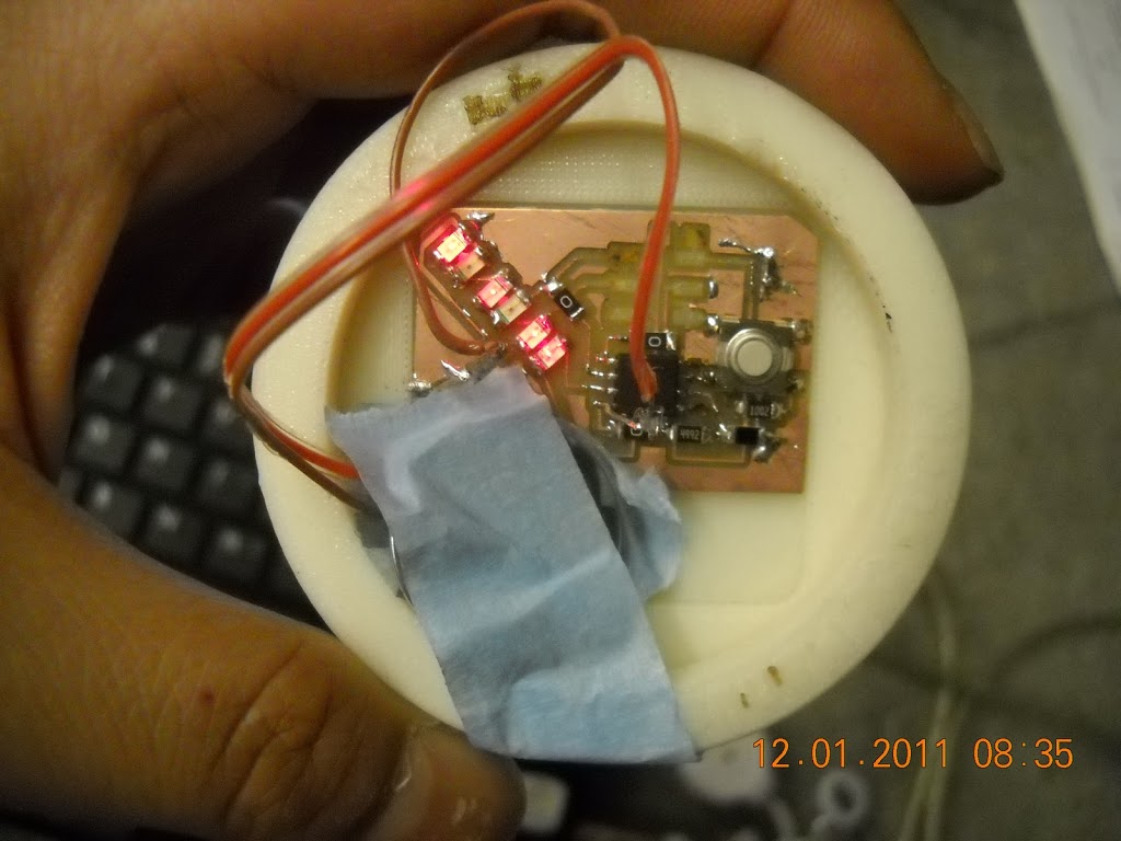
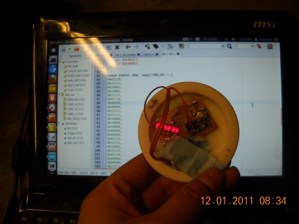
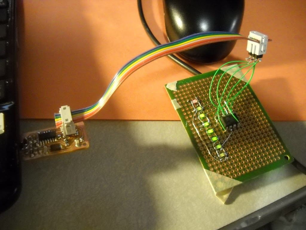
v0.1: 6 leds (3 pins), attiny45, phototrans, button, isp header (no battery) — board done.
v0.1 — code is the fails. I’ve been chasing this weird compiler bug for many days now.
So I milled and populated my eagle circuit and it works (well, the LEDs at least, haven’t tested buttons / phototransistor). https://github.com/nouyang/pov-yoyo and http://fab.cba.mit.edu/classes/4.140/people/nancy.ouyang/Week11/Week11.html
 |
| eagle schematic I’m using the ng.lbr, fab.lbr, and the sparkfun libraries. More info here: http://academy.cba.mit.edu/tutorials/eagle/eagle_resources.html and the list of parts in fab.lbr: http://fab.cba.mit.edu/about/fab/inv.html |
 |
| board layout |
 |
| slightly cleaned up, colors inverted, for milling out on the roland modella in the MIT Media Lab shop. I export at 1000 dpi to be safe, and clean it up in the open-source and free GIMP image editor. |
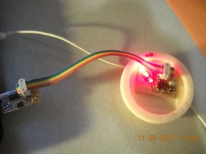 |
| powered off of USB for now. |
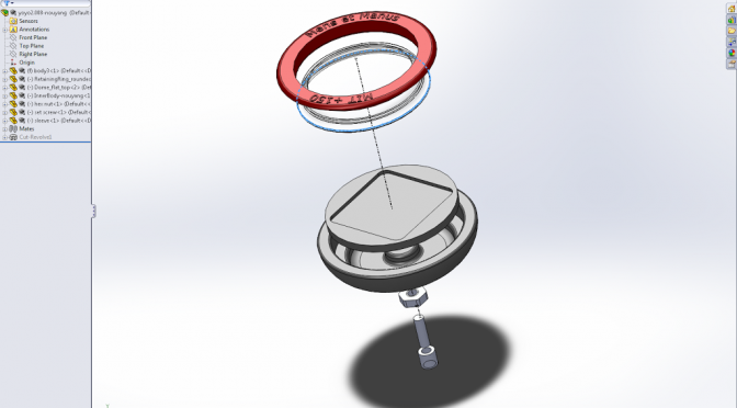
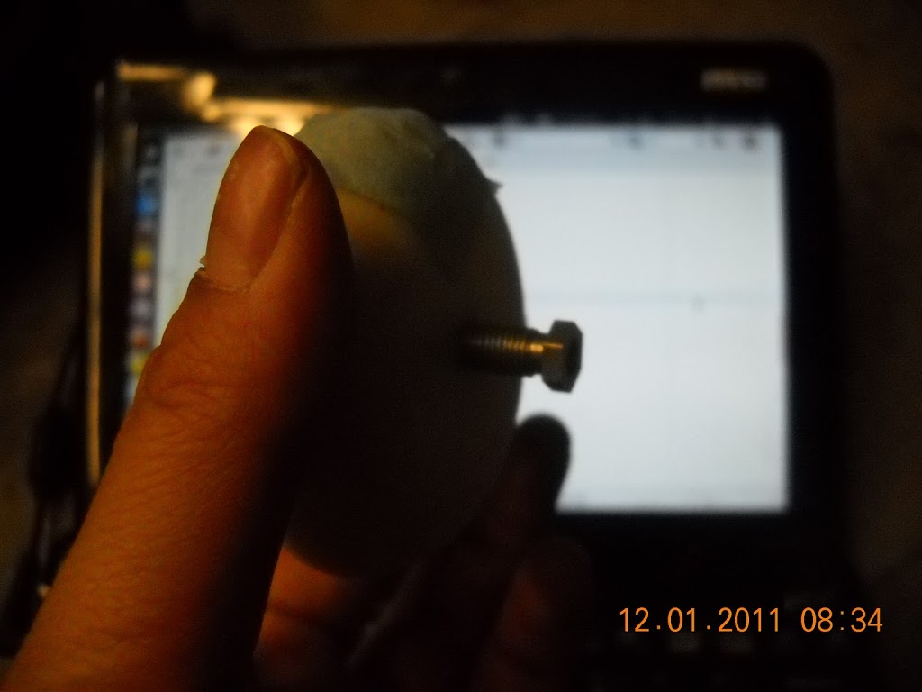
The yoyo is 3d printed, but it’s designed to be injection molded. I’m working with Laura Shumaker and Dan Fourie, and it’s based off of lshu’s 2.008 group’s yoyo design from last year. I’ll upload the Solidworks files when I get permission. Here’s what the CAD files look like (there are three parts. The PCB should pressfit inside the inner body, which fits inside the outer body, and the retaining ring goes on top, pressfitting into the outer body and making sure the inner body doesn’t come out).
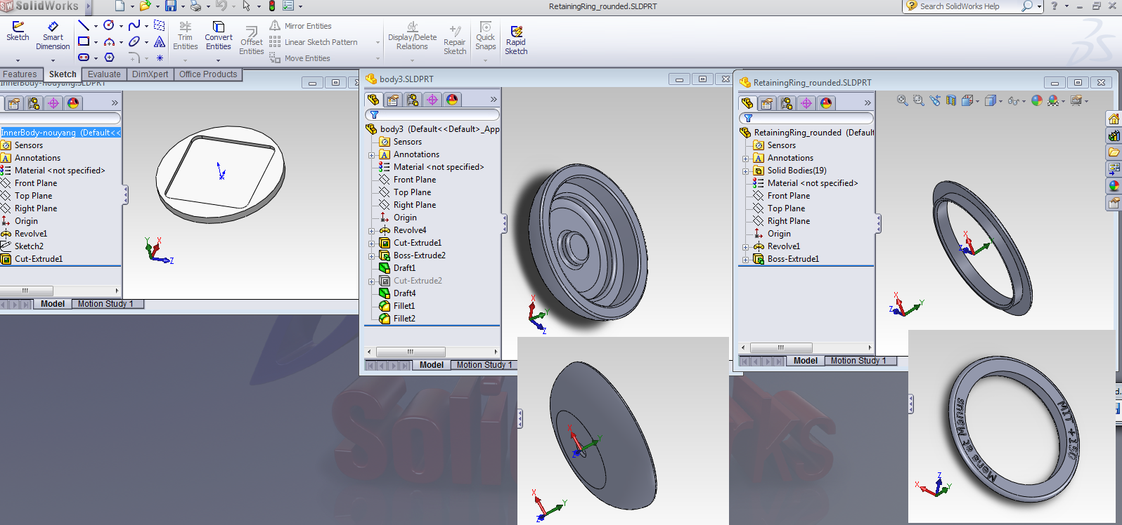 |
| The three parts that I 3d printed |
 |
| inner body determines dimensions of board. Corners filleted due to concern over injection molding mold machinability, but turns out to be unwarranted (I think), next version will have sharp corners. |
I ended up approximating in Eagle the dimensions from the CAD file that I would need to fit inside the
Anyway, so now I’m at the point where I can turn each LED on individually, I’m still trying to figure out my code bugs.
Oh right, this is after my realization last week that I don’t understand any codes. Not even hello world codes. 0b000? 0x000? 0? char? int? huh?
So, I read up on bit operations stuff -^-^-
I recommend these for explaining the hello world code, which seems straightforward now (turn LED on! turn off!) but seemed completely foreign when I was trying to debug my code / write my own / mash together code from other people.
[1] http://fab.cba.mit.edu/content/tools/microcontrollers/c_for_microcontrollers.html
[2] http://www.arduino.cc/playground/Code/BitMath
[3] http://iamsuhasm.wordpress.com/tutsproj/avr-gcc-tutorial/
My code’s here:
https://github.com/nouyang/pov-yoyo
and I’ll run over some things I hadn’t found clearly explained here.
0x designates hexadecimal, while 0b designates binary. These are fixed flags, similar to a plus or minus sign in front of a number. The actual values that matter come afterward.
So 0b0010 translates to, in decimal, two. And the compiler will assume that there are infinity zeros to the right (well, until ’till the size of the variable or constant at least, eg 0b00000010 for a byte = 8 bits), just as in decimal “2” and “00[…]002” are equivalent.
#define LINE_A 0
#define LINE_B 1
#define LINE_C 2
//DDRB direction config for each LED (1 = output) //in or output
const char led_dir[6] = {
( 1<<LINE_B | 1<<LINE_A & ~(1<<LINE_C)), //LED 0
( 1<<LINE_A | 1<<LINE_B & ~(1<<LINE_C)), //LED 1
[…]
};
//PORTB output config for each LED (1 = High, 0 = Low) //hi or lo
const char led_out[6] = {
( 1<<LINE_B & ~(1<<LINE_A)), //LED 0
[…]
};
What do these lines mean? Well,
1 << LINE_A means 1 << 0 according to the #defines : This means “put a 1 shifted over 0 bits”, aka 0b1 or 0b00000001
1 << 1 : 0b10, or 0b00000010
The “|” means bitwise OR, aka I add the two numbers together to get
0b00000011 — that is, DDRB pins 1 and 2 are both outputs and everything else is in high impedance mode. To be safe, since I am using 6 LEDs on 3 pins
 |
| http://en.wikipedia.org/wiki/Charlieplexing for more info |
and therefore cannot have uncertainty about whether the unused pin is in high impedance (input) mode or output mode, I explicitly state with
& ~(1<<LINE_C) that pin 7 (on the attiny45, see datasheet which tells me that pin7 corresponds to index 2 on DDRB — hence #defines LINE_C 2) must be in high impedance mode.
See [1] for an explanation of what & ~(a 1 at the appropriate index)
I’m not certain this is necessary, since in my case I explicitly say “DDRB = 0b011” later in the code rather than saying “DDRB |= 0b011” which would have left high any unspecified pins that were originally high, but I’d rather put it in here than risk wondering if my bugs are because of this.
Thus, an equivalent led_dir array could have said led_dir = {0b001, 0b011, […]}.
C Resources:
My code
Charlieplexing code:
Most PoV code appears to be in asm:

![Nyancat cake mold, working PoV [not so yoyo], vending corkscrew test (mod servo for continuous rotation)](https://orangenarwhals.com/wp-content/uploads/2012/10/DSCN3324-672x372.jpg)