i have been making a lot of things lately.
Never enough!
But yes, I rediscovered the lasercutter, and there happens to be one upstairs of MITERS now.*
* [I should really get a Real Laptop (that I can CAD on) and then I have no excuse to hang around upstairs when the MITERS computers are occupied. (or just set up another computer downstairs…) but in the meantime there are excellent computers are the third floor (which as a bonus are tucked away in corners. I have a special affinity for corners).]
My convoluted group loyalty issues aside, last week there was epic snowage, so much that MIT closed down. So then I decided to build a snowbot, or rather a screw-propelled vehicle.
http://en.wikipedia.org/wiki/Screw-propelled_vehicle
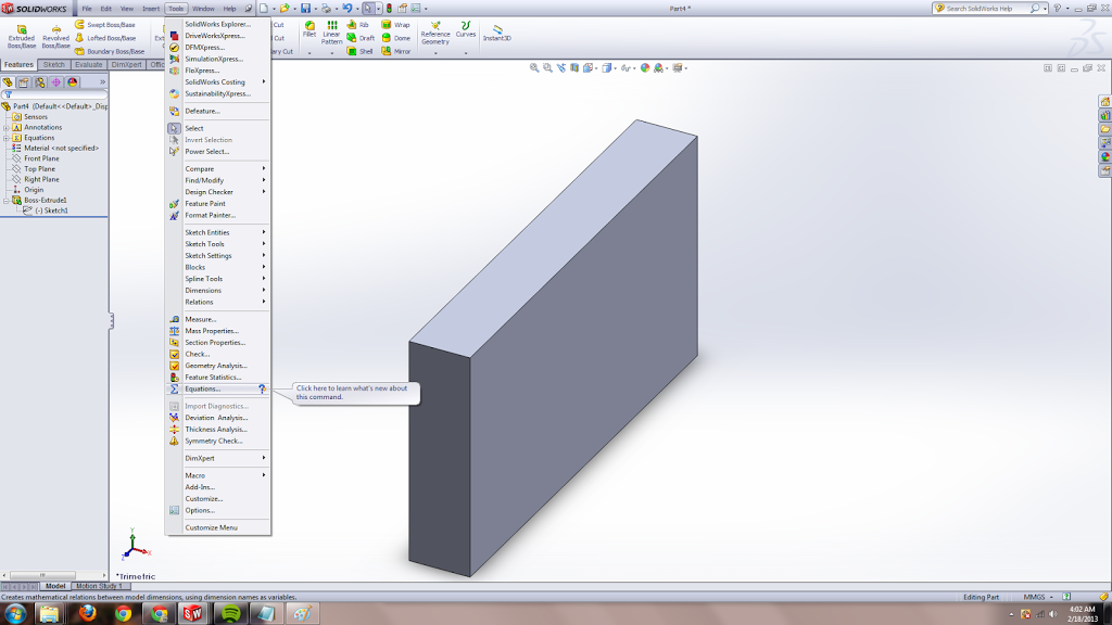
Turns out some excellent undergrad wrote a thesis on this topic, with pictures and build and equations!
http://www.wpi.edu/Pubs/E-project/Available/E-project-031411-150953/unrestricted/Ice_Inspection_Robot_MQP,_Final_Report.pdf
So he made his prototype out of PVC pipe. Specifically, giant!diameter!PVC pipe for the augur and 1/4” diameter pipe wound around the large pipe for the threads on the augur. His second revision was tube aluminum with specialty-ordered sheet steel threads (the two were held together with “Loctite E-20NS metal epoxy”. Wow. Heavy-duty epoxy).
Well! I wanted to complete snow-bot in a day so I decided to make it out of coke can + cat 5 cable hotglued onto it (with revision two to be 3d printed).
 |
| that is so totally a workable augur. right? |
This err didn’t happen. I got distracted by other lasercut projects. But yea, the plan was to attach two continuous rotation servos to turn the coke cans and voila, I would have instant prototype.
note: for the sake of sleep this is going to be an overview post with more detailed / better formatted / all my files–posts to come, but in case I don’t get around to those:
My first step was to discover that I had SpringerRC continuous rotation servos, perfect for the job, but no servo horns. (First of all, note that servo horns are NOT all compatible). Oh noes! Well. Turns out, they are pretty easy to make, despite the total lack of help from this site which just says “lol they are easy to make”:
http://makeprojects.com/Wiki/Servos
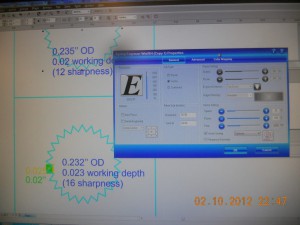
A bit of googling and double-checking by counting by hand, I find out futaba-compatible horns have 25 “teeth.” And using calipers I determine the outer and estimate the inner diameter, for which I get roughly 0.02” which order-of-magnitude agrees with the super-accurate measurements made by this dude.
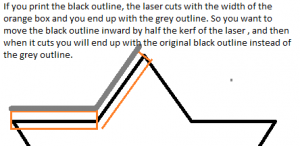
I also, via the internet (and later by trial-and-error) find 3mm acrylic-like plastic to have a kerf of about 0.005”.
So using coreldraw (or inkscape), there is a polygon/star tool, and I enter 25 pointed star. I then eye-ball the “sharpness” parameter, which you have a bit of slack on (the horn teeth just needs to fit between the servo teeth). I also initially set the x-y width to be 0.235”, the exact outer-diameter I measured. When cut out, this servo horn a bit loose but slides onto the servo and turns the servo when it is turned.
 |
| yes. my camera has a permanent dust speck somewhere inside it… |
Then I iterate. You can see I drew a green and yellow rectangle, for 0.02” + 0.005” kerf, to get the “sharpness” (pointiness of the star) setting right (if you draw it out, to account for kerf, the OD of the star should be smaller by 1/2 kerf and possibly the star’s inner corners should go 1/2 kerf deeper, hence why 16 sharpness with the inner corner somewhere between the length of the green and yellow rectangles. I’m not 100% how sharpness is interconnected with the diameter of the star so it’s hard to say what the exact adjustment should be).
 |
| f* yea MS Paint |
The laser settings I used for a 120W epilog laser:
Of course, I don’t finish over the weekend and Monday I walk into 2.007 lab (which I am undergrad assisting with, UAing, this term) and there are a gazillion springerRC servos and servo horns. But that’s beside the point.
I also realized that part of my search criteria for LIFE aka a career included “access to lasercutter,” but maybe I am supposed to look for a job that pays well so that I can buy my own lasercutter. Hrm.
Hrm…
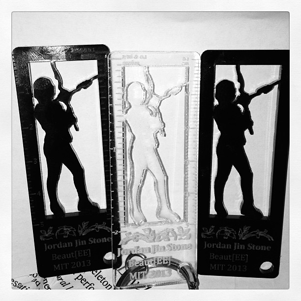
Anyway, what else happened? Oh right, Jordan‘s birthday came up. Because she is awesome, I decided I should make her a birthday gift. Inspired by Kat Struckmann’s cruftmas (putz hall secret santa tradition where gift has to be entirely made of cruft, aka free stuff. Oh right, I made a sheet steel bookstand for my secret santa and learned the importance of product design, because the gal I gave it to was like “wtf is this, a shelf?” ^^; #toblogabout) gift to Sterling Harper, aka by the Archer TV show:
 |
| image courtesy of jordan. |
Oh gosh. I had to use so many programs to make this, I don’t even. No. Anyway, the general idea is to use various selection tools (oh robutts don’t use the polygon tool by itself, it’s so easy to accidentally hit escape and erase all your work with the selection, make sure to use quick-mask model with shift-Q — everything this is orange is not in the selection and everything that is white is) in GIMP on the original image (see: her blog), export selection to path, save path as an SVG, import that into inkscape, use various path tools (difference, something like that) to merge the Person outline with the rectangle outline that I want to cut out to create a stencil-like effect, realize that coreldraw hates inkscape SVGs for whatever reason, save inkscape file as PDF and import and clean up import in coreldraw, still recreate a lot of the work in coreldraw because I am more familiar with sending coreldraw files to the lasercutter, find flowers on openclipart, and then spend a few hours playing around with the DPI / whatever settings because I want to get a raster image of the photograph etched onto the outline. This… doesn’t go so well. Somewhere along the way I decide to add a ruler to the thing, because really, useless keychains may as well have rulers on them. I discover the magical coreldraw “blend” tool, where I can just draw two lines at the beginning and end and then specify how many copies I want to use to blend between them (since the end and beginning lines are the same, all the intermediates are the same as well).
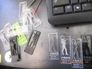 |
| so many rejects. luckily this is all from small bits of scrap other people would probably just throw right out. |
Then there were other lasercutter shenanigans, but that’s for another time. Briefly…
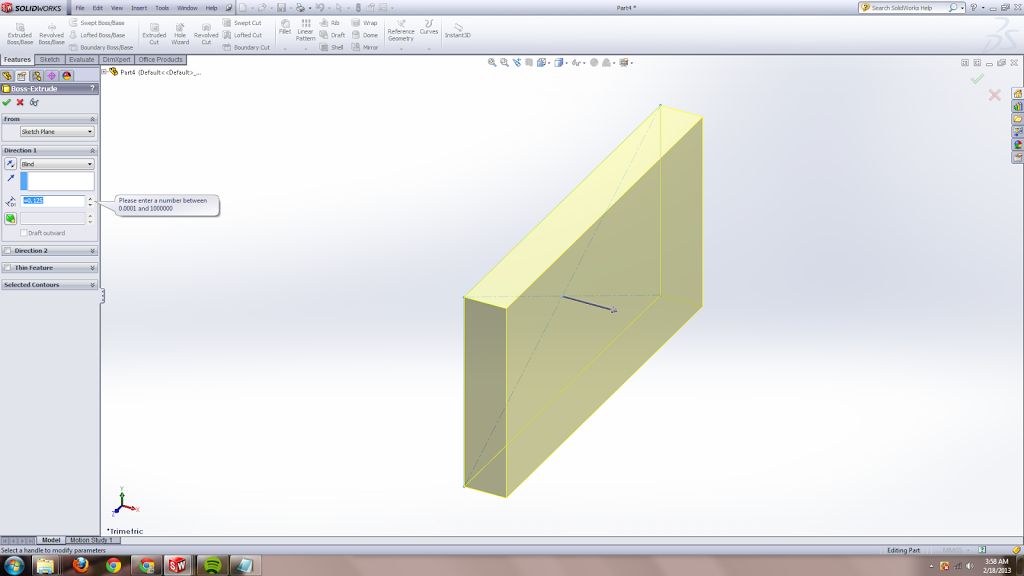
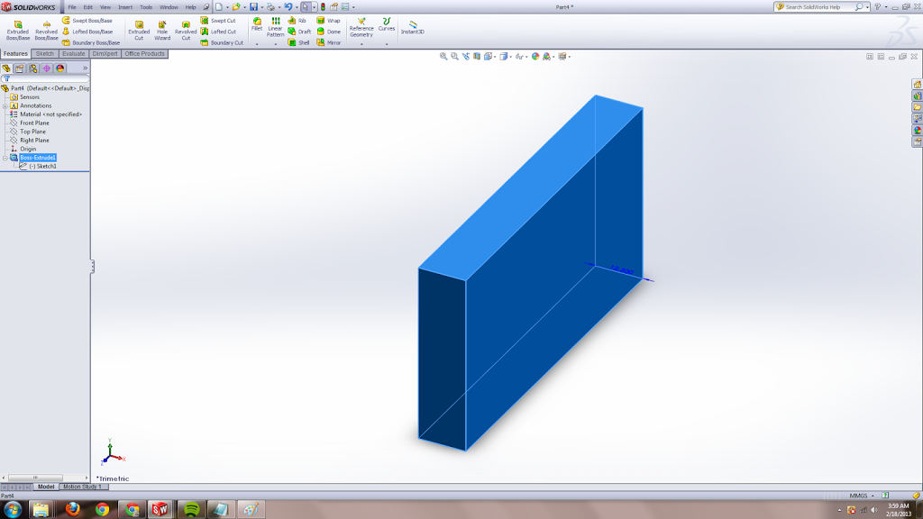
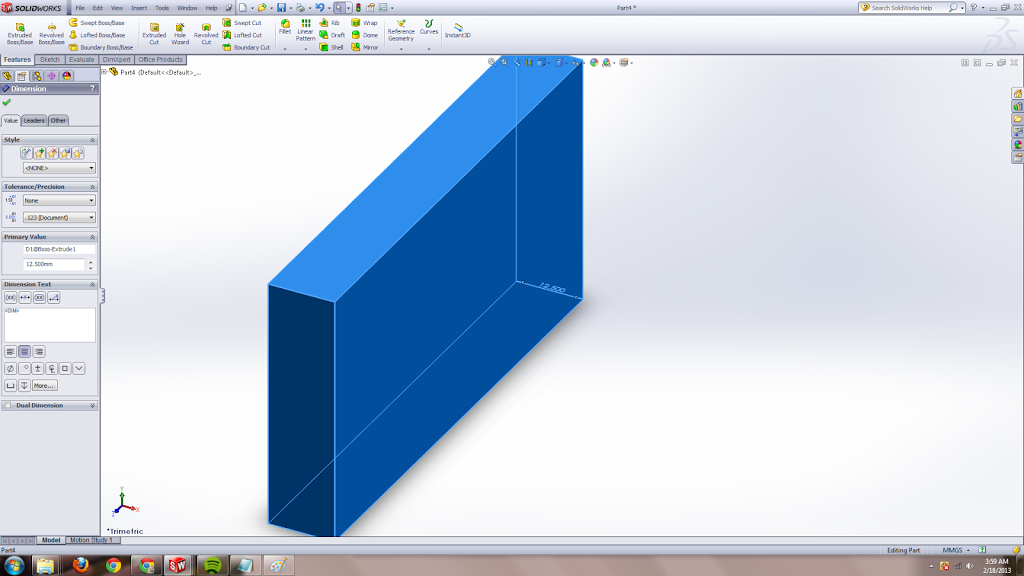
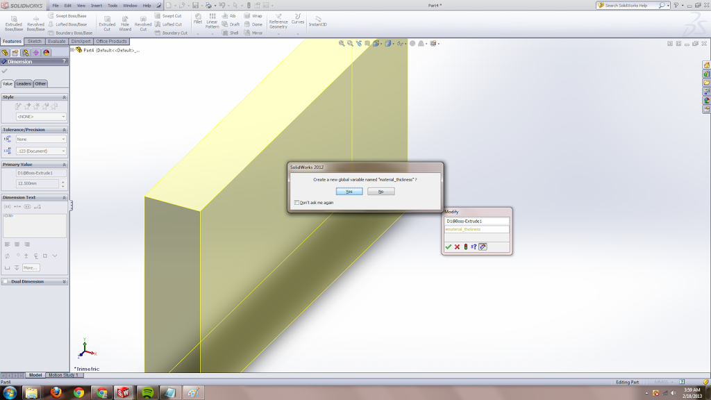
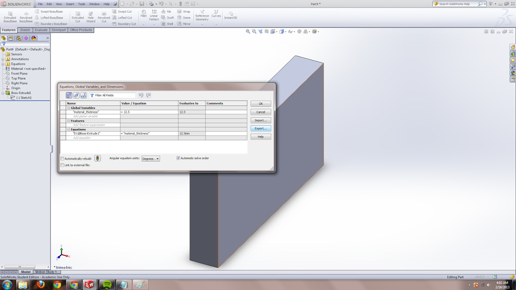
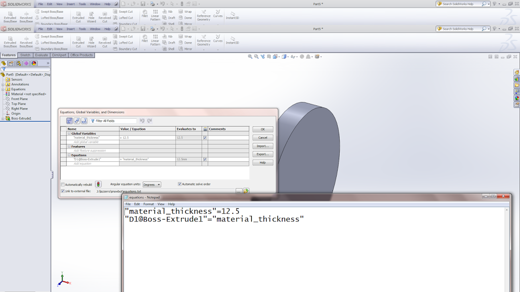
Oh gosh that is a topic in and of itself. Inkscape has a gear generator, but then I tried to x-y scale that, so the pitch becomes something strange, and then I import that dxf into solidworks to make a 3d model and also to measure the pitch and other things, and later export it as a dxf from solidworks to coreldraw … … apparently solidworks has a gear generator in its toolbox. I should use that next time.
Oh, food-wise:
Oh also this excellent post on designing sninges, aka how to make acrylic bend:
http://blog.makezine.com/2011/12/08/designing-sninges-in-laser-cut-acrylic/
Guys I should just go do lasercut etsy things. Forget scaling and engineering, and go be a craftsperson >__>;; and sell things at cons or something.
Oh and speaking of bending acrylic,
Hrm this is rich with possibilities. I CAN EMBED SO MUCH ELECTRONICS IN HERE with this 3d possibility.
Heck I could like embed a mini hexapod in there probably. With a button. So I can hit the button and pop out a small hexapod army from brace/ankle-lets.
HRM.
Hexapod armies.
*reminds self to talk about microcenter and finding hexy, the kickstarter project funded just seven months ago, on the shelves there….* #toblogabout
Okay, when my blog posts get to the topic of hexapod armies it’s a definite sign that I am procrastinating. Time to get back to CADing snowbot. (CADing a spontaneous robot? wtf? MIT, what have you done to me, that I would prefer to CAD and lasercut something instead of putting things together by hand until it works…)
==
additional resource: list of screws, in case you lose those screws for the horns:
http://www.rcgroups.com/forums/showthread.php?t=914983


